Dell PowerConnect J-8208 Hardware Guide - Page 56
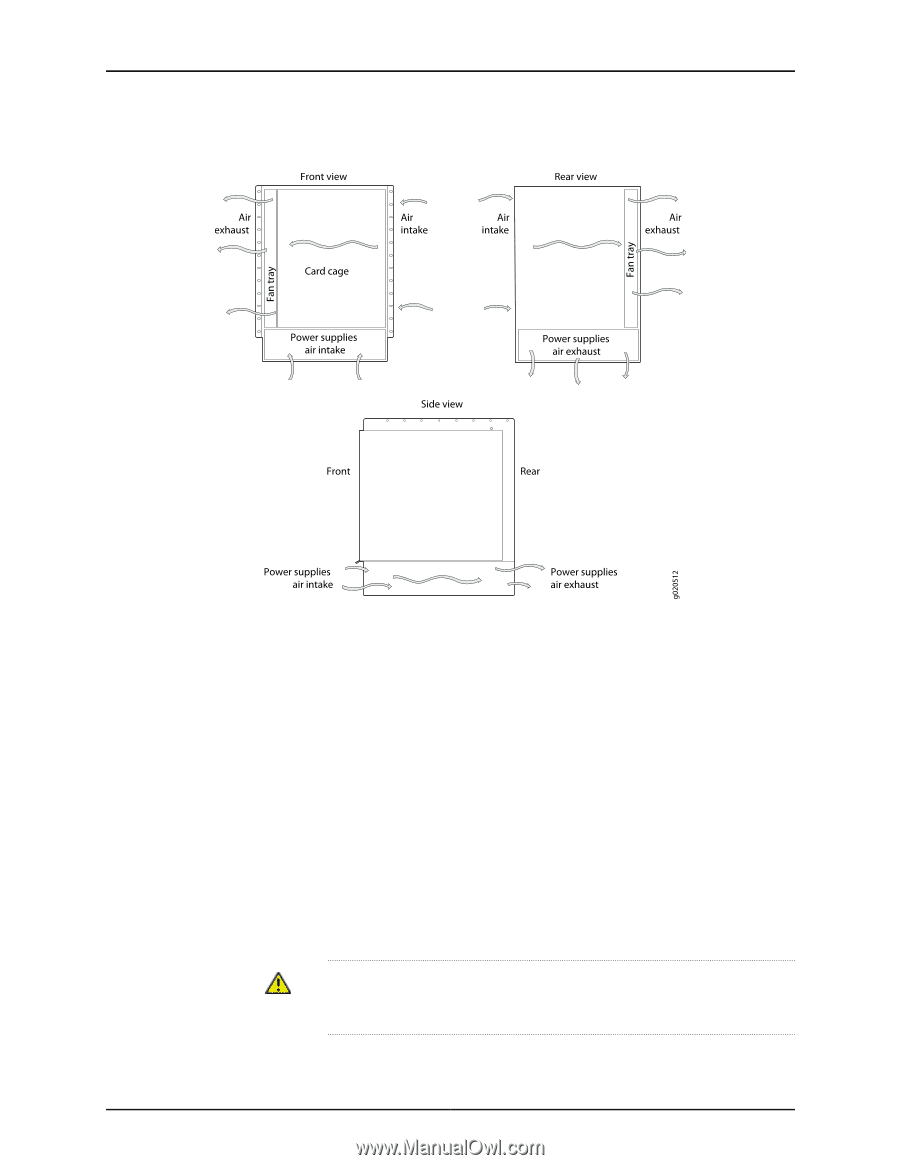
Airflow Through the J-EX8208 Switch Chassis
 |
View all Dell PowerConnect J-8208 manuals
Add to My Manuals
Save this manual to your list of manuals |
Page 56 highlights
Dell PowerConnect J-Series J-EX8208 Ethernet Switch Hardware Guide Figure 25: Airflow Through the J-EX8208 Switch Chassis The Switch Fabric and Routing Engine (SRE) module monitors the temperature of switch components. Under normal operating conditions, the fans in the fan tray run at less than full speed. The fans are controlled by two fan tray controllers. The fans are numbered 1 through 12. Fans 1 through 6 are controlled by the first fan tray controller. Fans 7 through 12 are controlled by the second fan tray controller. If one fan tray controller fails, the other fan tray controller keeps half the fans working. This allows the switch to continue to operate normally as long as the remaining fans cool the chassis sufficiently. If a fan fails or the ambient temperature rises above the threshold 113°F (45°C), the speed of the remaining fans is automatically adjusted to keep the temperature within the acceptable range, 32°F (0°C) through 104°F (40°C). The fan tray continues to operate indefinitely and provide sufficient cooling even when a single fan fails provided the room temperature is within the operating range. You can check the status of fans and the chassis temperature from the Environment Status option in the Status menu on the LCD panel. See "LCD Panel in a J-EX8200 Switch" on page 15. You cannot replace a single fan. If one or more fans fail, you must replace the entire fan tray. WARNING: There is no fan guard on the fans. Be careful to keep your fingers clear of moving fan blades when you are removing the fan tray. 40
-
 1
1 -
2
-
3
-
4
-
5
-
6
-
7
-
8
-
9
-
10
-
11
-
12
-
13
-
14
-
15
-
16
-
17
-
18
-
19
-
20
-
21
-
22
-
23
-
24
-
25
-
26
-
27
-
28
-
29
-
30
-
31
-
32
-
33
-
34
-
35
-
36
-
37
-
38
-
39
-
40
-
41
-
42
-
43
-
44
-
45
-
46
-
47
-
48
-
49
-
50
-
 51
51 -
 52
52 -
 53
53 -
 54
54 -
 55
55 -
 56
56 -
 57
57 -
 58
58 -
 59
59 -
 60
60 -
 61
61 -
62
-
63
-
64
-
65
-
66
-
67
-
68
-
69
-
70
-
71
-
72
-
73
-
74
-
75
-
76
-
77
-
78
-
79
-
80
-
81
-
82
-
83
-
84
-
85
-
86
-
87
-
88
-
89
-
90
-
91
-
92
-
93
-
94
-
95
-
96
-
97
-
98
-
99
-
100
-
101
-
102
-
103
-
104
-
105
-
106
-
107
-
108
-
109
-
110
-
111
-
112
-
113
-
114
-
115
-
116
-
117
-
118
-
119
-
120
-
121
-
122
-
123
-
124
-
125
-
126
-
127
-
128
-
129
-
130
-
131
-
132
-
133
-
134
-
135
-
136
-
137
-
138
-
139
-
140
-
141
-
142
-
143
-
144
-
145
-
146
-
147
-
148
-
149
-
150
-
151
-
152
-
153
-
154
-
155
-
156
-
157
-
158
-
159
-
160
-
161
-
162
-
163
-
164
-
165
-
166
-
167
-
168
-
169
-
170
-
171
-
172
-
173
-
174
-
175
-
176
-
177
-
178
-
179
-
180
-
181
-
182
-
183
-
184
-
185
-
186
-
187
-
188
-
189
-
190
-
191
-
192
-
193
-
194
-
195
-
196
-
197
-
198
-
199
-
200
-
201
-
202
-
203
-
204
-
205
-
206
-
207
-
208
-
209
-
210
-
211
-
212
-
213
-
214
-
215
-
216
-
217
-
218
-
219
-
220
-
221
-
222
-
223
-
224
-
225
-
226
-
227
-
228
-
229
-
230
-
231
-
232
-
233
-
234
-
235
-
236
-
237
-
238
-
239
-
240
-
241
-
242
-
243
-
244
-
245
-
246
-
247
-
248
-
249
-
250
-
251
-
252
-
253
-
254
-
255
-
256
-
257
-
258
-
259
-
260
-
261
-
262
-
263
-
264
-
265
-
266
-
267
-
268
-
269
-
270
-
271
-
272
-
273
-
274
-
275
-
276
 |
 |