Dell PowerConnect J-8208 Hardware Guide - Page 38
Switch Fabric and Routing Engine (SRE) Module in a J-EX8208 Switch
 |
View all Dell PowerConnect J-8208 manuals
Add to My Manuals
Save this manual to your list of manuals |
Page 38 highlights
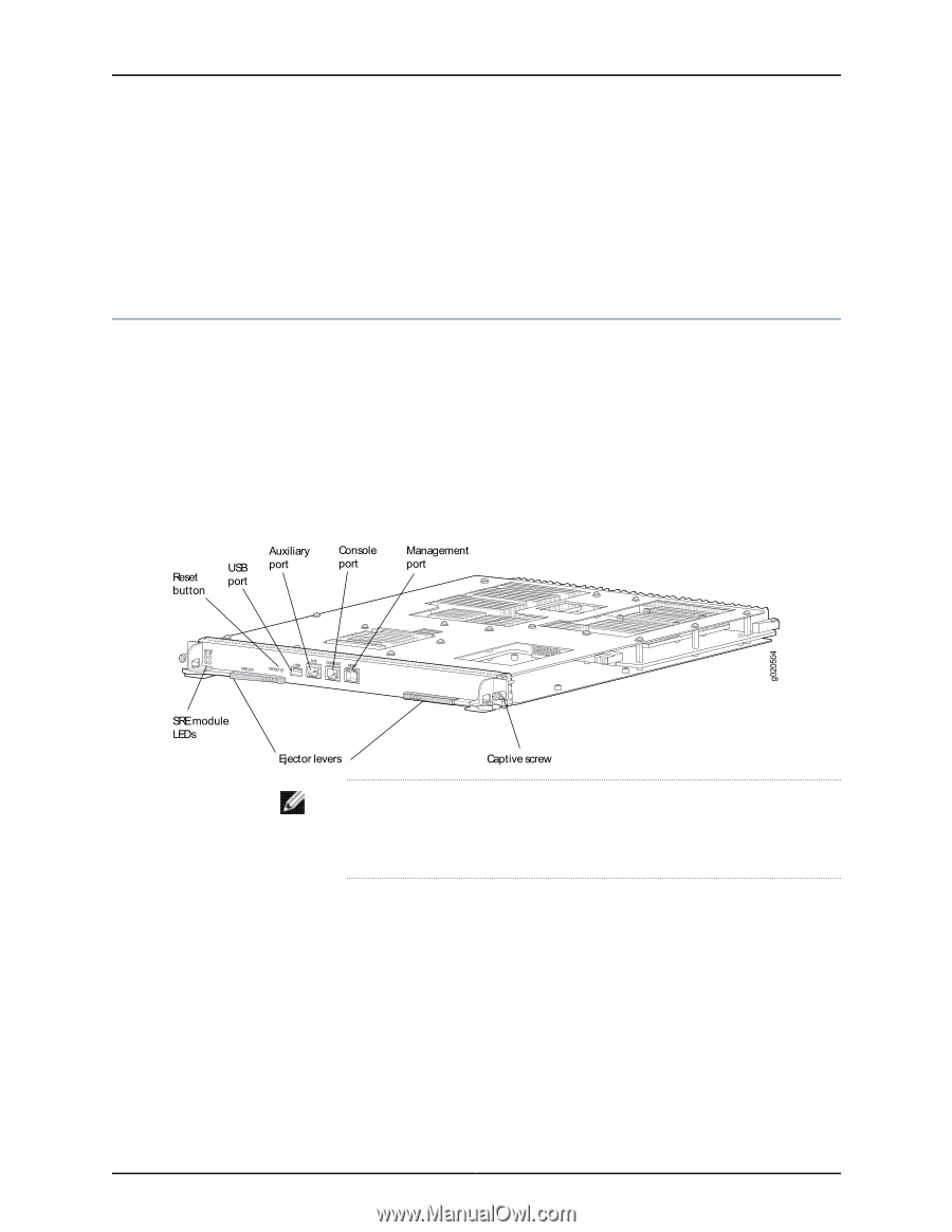
Dell PowerConnect J-Series J-EX8208 Ethernet Switch Hardware Guide • Removing a Line Card from a J-EX8200 Switch on page 170 • Removing an AC Power Supply from a J-EX8200 Switch on page 161 • Removing a Fan Tray from a J-EX8208 Switch on page 163 • Removing a Transceiver from a J-EX Series Switch on page 173 Switch Fabric and Routing Engine (SRE) Module in a J-EX8208 Switch The Switch Fabric and Routing Engine (SRE) module performs switching and system management functions in a J-EX8208 switch. See Figure 7 on page 22. A J-EX8208 switch has two SRE modules for Routing Engine and switch control redundancy. See "Understanding J-EX8208 Switch Component and Functionality Redundancy" on page 9. The SRE modules install horizontally into the front of the chassis in slots labeled SRE0 and SRE1. Figure 7: SRE Module in a J-EX8208 Switch NOTE: We recommend that you install two SRE modules for redundancy. If you install only one SRE module, we recommend that you install it in slot SRE0. See "Slot Numbering for a J-EX8208 Switch" on page 11. When two SRE modules are installed, one functions as the master and the other acts as the backup. If the master SRE module fails or is removed, the backup takes over as the master. When two SRE modules are installed, the backup SRE module is hot-insertable and hot-removable, but the master SRE module is hot-pluggable. If only one SRE module is installed, you must halt the SRE module before removing it. The SRE module provides these functions: • Provides full fabric connectivity to all line cards installed in the chassis • Through the switching plane, provides switching functionality to the switch 22
-
 1
1 -
2
-
3
-
4
-
5
-
6
-
7
-
8
-
9
-
10
-
11
-
12
-
13
-
14
-
15
-
16
-
17
-
18
-
19
-
20
-
21
-
22
-
23
-
24
-
25
-
26
-
27
-
28
-
29
-
30
-
31
-
32
-
 33
33 -
 34
34 -
 35
35 -
 36
36 -
 37
37 -
 38
38 -
 39
39 -
 40
40 -
 41
41 -
 42
42 -
 43
43 -
44
-
45
-
46
-
47
-
48
-
49
-
50
-
51
-
52
-
53
-
54
-
55
-
56
-
57
-
58
-
59
-
60
-
61
-
62
-
63
-
64
-
65
-
66
-
67
-
68
-
69
-
70
-
71
-
72
-
73
-
74
-
75
-
76
-
77
-
78
-
79
-
80
-
81
-
82
-
83
-
84
-
85
-
86
-
87
-
88
-
89
-
90
-
91
-
92
-
93
-
94
-
95
-
96
-
97
-
98
-
99
-
100
-
101
-
102
-
103
-
104
-
105
-
106
-
107
-
108
-
109
-
110
-
111
-
112
-
113
-
114
-
115
-
116
-
117
-
118
-
119
-
120
-
121
-
122
-
123
-
124
-
125
-
126
-
127
-
128
-
129
-
130
-
131
-
132
-
133
-
134
-
135
-
136
-
137
-
138
-
139
-
140
-
141
-
142
-
143
-
144
-
145
-
146
-
147
-
148
-
149
-
150
-
151
-
152
-
153
-
154
-
155
-
156
-
157
-
158
-
159
-
160
-
161
-
162
-
163
-
164
-
165
-
166
-
167
-
168
-
169
-
170
-
171
-
172
-
173
-
174
-
175
-
176
-
177
-
178
-
179
-
180
-
181
-
182
-
183
-
184
-
185
-
186
-
187
-
188
-
189
-
190
-
191
-
192
-
193
-
194
-
195
-
196
-
197
-
198
-
199
-
200
-
201
-
202
-
203
-
204
-
205
-
206
-
207
-
208
-
209
-
210
-
211
-
212
-
213
-
214
-
215
-
216
-
217
-
218
-
219
-
220
-
221
-
222
-
223
-
224
-
225
-
226
-
227
-
228
-
229
-
230
-
231
-
232
-
233
-
234
-
235
-
236
-
237
-
238
-
239
-
240
-
241
-
242
-
243
-
244
-
245
-
246
-
247
-
248
-
249
-
250
-
251
-
252
-
253
-
254
-
255
-
256
-
257
-
258
-
259
-
260
-
261
-
262
-
263
-
264
-
265
-
266
-
267
-
268
-
269
-
270
-
271
-
272
-
273
-
274
-
275
-
276
 |
 |