Dell PowerConnect J-8208 Hardware Guide - Page 132
Installing a Fan Tray in a J-EX8208 Switch
 |
View all Dell PowerConnect J-8208 manuals
Add to My Manuals
Save this manual to your list of manuals |
Page 132 highlights
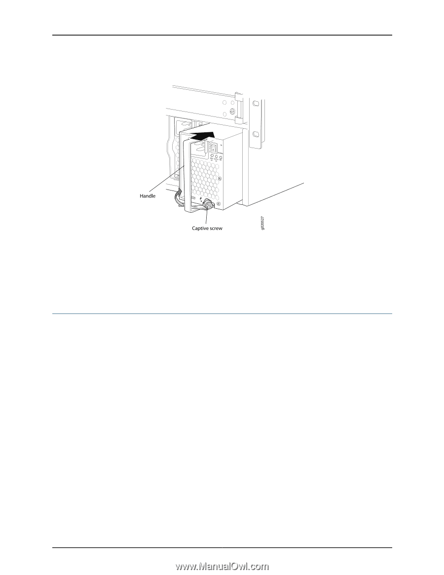
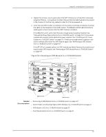
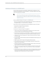
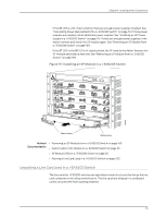
Dell PowerConnect J-Series J-EX8208 Ethernet Switch Hardware Guide Figure 54: Installing an AC Power Supply in a J-EX8200 Switch Related • Removing an AC Power Supply from a J-EX8200 Switch on page 161 Documentation • Calculating Power Requirements for a J-EX8208 Switch on page 79 • Field-Replaceable Units in a J-EX8208 Switch on page 21 • AC Power Supply in a J-EX8200 Switch on page 34 Installing a Fan Tray in a J-EX8208 Switch A J-EX8208 switch has a single, field-replaceable fan tray. The fan tray is a hot-insertable and hot-removable field-replaceable unit (FRU); you can remove and replace the fan tray while the switch is running without turning off power to the switch or disrupting switching functions. The fan tray installs vertically on the left side on the front of the chassis. A handle on the front faceplate facilitates handling of the fan tray. There is a spring-loaded latch on the base of the fan tray that is used to latch the fan tray into the chassis. Before you begin to install a fan tray: • Ensure you understand how to prevent ESD damage. See "Prevention of Electrostatic Discharge Damage on J-EX Series Switches" on page 236. Ensure that you have the following parts and tools available to install a fan tray in a J-EX8208 switch: 116
-
 1
1 -
2
-
3
-
4
-
5
-
6
-
7
-
8
-
9
-
10
-
11
-
12
-
13
-
14
-
15
-
16
-
17
-
18
-
19
-
20
-
21
-
22
-
23
-
24
-
25
-
26
-
27
-
28
-
29
-
30
-
31
-
32
-
33
-
34
-
35
-
36
-
37
-
38
-
39
-
40
-
41
-
42
-
43
-
44
-
45
-
46
-
47
-
48
-
49
-
50
-
51
-
52
-
53
-
54
-
55
-
56
-
57
-
58
-
59
-
60
-
61
-
62
-
63
-
64
-
65
-
66
-
67
-
68
-
69
-
70
-
71
-
72
-
73
-
74
-
75
-
76
-
77
-
78
-
79
-
80
-
81
-
82
-
83
-
84
-
85
-
86
-
87
-
88
-
89
-
90
-
91
-
92
-
93
-
94
-
95
-
96
-
97
-
98
-
99
-
100
-
101
-
102
-
103
-
104
-
105
-
106
-
107
-
108
-
109
-
110
-
111
-
112
-
113
-
114
-
115
-
116
-
117
-
118
-
119
-
120
-
121
-
122
-
123
-
124
-
125
-
126
-
 127
127 -
 128
128 -
 129
129 -
 130
130 -
 131
131 -
 132
132 -
 133
133 -
 134
134 -
 135
135 -
 136
136 -
 137
137 -
138
-
139
-
140
-
141
-
142
-
143
-
144
-
145
-
146
-
147
-
148
-
149
-
150
-
151
-
152
-
153
-
154
-
155
-
156
-
157
-
158
-
159
-
160
-
161
-
162
-
163
-
164
-
165
-
166
-
167
-
168
-
169
-
170
-
171
-
172
-
173
-
174
-
175
-
176
-
177
-
178
-
179
-
180
-
181
-
182
-
183
-
184
-
185
-
186
-
187
-
188
-
189
-
190
-
191
-
192
-
193
-
194
-
195
-
196
-
197
-
198
-
199
-
200
-
201
-
202
-
203
-
204
-
205
-
206
-
207
-
208
-
209
-
210
-
211
-
212
-
213
-
214
-
215
-
216
-
217
-
218
-
219
-
220
-
221
-
222
-
223
-
224
-
225
-
226
-
227
-
228
-
229
-
230
-
231
-
232
-
233
-
234
-
235
-
236
-
237
-
238
-
239
-
240
-
241
-
242
-
243
-
244
-
245
-
246
-
247
-
248
-
249
-
250
-
251
-
252
-
253
-
254
-
255
-
256
-
257
-
258
-
259
-
260
-
261
-
262
-
263
-
264
-
265
-
266
-
267
-
268
-
269
-
270
-
271
-
272
-
273
-
274
-
275
-
276
 |
 |