Dell PowerConnect J-8208 Hardware Guide - Page 25
Understanding J-EX8208 Switch Component and Functionality Redundancy
 |
View all Dell PowerConnect J-8208 manuals
Add to My Manuals
Save this manual to your list of manuals |
Page 25 highlights
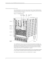
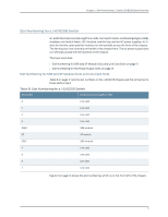
Chapter 1: Dell PowerConnect J-Series J-EX8208 Switch Overview • Mounting a J-EX8208 Switch on a Rack or Cabinet on page 101 • Installing and Removing J-EX8208 Switch Hardware Components on page 113 Understanding J-EX8208 Switch Component and Functionality Redundancy The J-EX8208 Ethernet switch is available as a fully redundant system. A redundant J-EX8208 switch configuration is designed so that no single point of failure can cause the entire switch to fail. See "J-EX8208 Switch Configurations" on page 6. This topic describes: • Hardware Components That Provide Redundancy on page 9 • Routing Engine and Control Redundancy on page 10 • Switch Fabric Redundancy on page 10 Hardware Components That Provide Redundancy The following hardware components provide redundancy to a J-EX8208 switch: • SRE modules-A redundant J-EX8208 switch has two Switch Fabric and Routing Engine (SRE) modules. When two SRE modules are installed, one SRE module functions as the master and the other functions as the backup. If the master SRE module fails or is removed the backup module takes over as the master SRE module. When the SRE modules are configured for graceful switchover, the backup SRE module automatically synchronizes its configuration and state with those of the master SRE module. Any update to the master SRE module is replicated on the backup SRE module. If the backup module assumes mastership, packet forwarding continues through the switch. • Power supplies-You can install up to six AC power supplies in a J-EX8208 switch. Each power supply connects to the backplane of the chassis, which distributes the output power produced by the power supplies to different switch components. (See "Backplane in a J-EX8208 Switch" on page 41.) Each power supply provides power to all the components in the switch. An N+1 power configuration is required for J-EX8200 Ethernet switches. In an N+1 power configuration, if one power supply fails or is removed, the remaining power supplies continue to supply power for the entire system without interruption. If dual power feed redundancy is required, the required power configuration is N+N. See "AC Power Supply in a J-EX8200 Switch" on page 34. • Cooling system-The cooling system in a J-EX8200 switch consists of a single fan tray. The fan tray contains 12 fans. Under normal operating conditions, the fans in the fan tray run at less than full speed. The fans are controlled by two fan tray controllers. The fans are numbered 1 through 12. Fans 1 through 6 are controlled by the first fan tray controller. Fans 7 through 12 are controlled by the second fan tray controller. If one fan tray controller fails, the other fan tray controller keeps half the fans working. This allows the switch to continue to operate normally as long as the remaining fans cool the chassis sufficiently. 9
-
 1
1 -
2
-
3
-
4
-
5
-
6
-
7
-
8
-
9
-
10
-
11
-
12
-
13
-
14
-
15
-
16
-
17
-
18
-
19
-
 20
20 -
 21
21 -
 22
22 -
 23
23 -
 24
24 -
 25
25 -
 26
26 -
 27
27 -
 28
28 -
 29
29 -
 30
30 -
31
-
32
-
33
-
34
-
35
-
36
-
37
-
38
-
39
-
40
-
41
-
42
-
43
-
44
-
45
-
46
-
47
-
48
-
49
-
50
-
51
-
52
-
53
-
54
-
55
-
56
-
57
-
58
-
59
-
60
-
61
-
62
-
63
-
64
-
65
-
66
-
67
-
68
-
69
-
70
-
71
-
72
-
73
-
74
-
75
-
76
-
77
-
78
-
79
-
80
-
81
-
82
-
83
-
84
-
85
-
86
-
87
-
88
-
89
-
90
-
91
-
92
-
93
-
94
-
95
-
96
-
97
-
98
-
99
-
100
-
101
-
102
-
103
-
104
-
105
-
106
-
107
-
108
-
109
-
110
-
111
-
112
-
113
-
114
-
115
-
116
-
117
-
118
-
119
-
120
-
121
-
122
-
123
-
124
-
125
-
126
-
127
-
128
-
129
-
130
-
131
-
132
-
133
-
134
-
135
-
136
-
137
-
138
-
139
-
140
-
141
-
142
-
143
-
144
-
145
-
146
-
147
-
148
-
149
-
150
-
151
-
152
-
153
-
154
-
155
-
156
-
157
-
158
-
159
-
160
-
161
-
162
-
163
-
164
-
165
-
166
-
167
-
168
-
169
-
170
-
171
-
172
-
173
-
174
-
175
-
176
-
177
-
178
-
179
-
180
-
181
-
182
-
183
-
184
-
185
-
186
-
187
-
188
-
189
-
190
-
191
-
192
-
193
-
194
-
195
-
196
-
197
-
198
-
199
-
200
-
201
-
202
-
203
-
204
-
205
-
206
-
207
-
208
-
209
-
210
-
211
-
212
-
213
-
214
-
215
-
216
-
217
-
218
-
219
-
220
-
221
-
222
-
223
-
224
-
225
-
226
-
227
-
228
-
229
-
230
-
231
-
232
-
233
-
234
-
235
-
236
-
237
-
238
-
239
-
240
-
241
-
242
-
243
-
244
-
245
-
246
-
247
-
248
-
249
-
250
-
251
-
252
-
253
-
254
-
255
-
256
-
257
-
258
-
259
-
260
-
261
-
262
-
263
-
264
-
265
-
266
-
267
-
268
-
269
-
270
-
271
-
272
-
273
-
274
-
275
-
276
 |
 |