Dell PowerConnect J-8208 Hardware Guide - Page 171
Removing a Round-Hole Cage Nut Clip Nut
 |
View all Dell PowerConnect J-8208 manuals
Add to My Manuals
Save this manual to your list of manuals |
Page 171 highlights
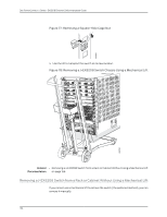
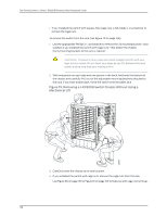
Chapter 12: Removing the Switch • Read "General Safety Guidelines and Warnings for J-EX Series Switches" on page 207, with particular attention to "Chassis Lifting Guidelines for J-EX8200 Switches" on page 220. • Ensure that the switch has been safely powered off (see "Powering Off a J-EX8200 Switch" on page 151) and that you have unplugged (disconnected) the power cords to the power supplies. • Ensure that you have disconnected any cables or wires attached to the switch ports. CAUTION: When removing more than one switch from a rack or cabinet, remove the switch in the top of the rack or cabinet first and proceed to remove the rest of the switches from top to bottom. Ensure that you have the following parts and tools available to remove the switch: • A mechanical lift • A Phillips (+) screwdriver, number 2 or number 3, depending on the size of your rack mounting screws • If you installed the switch with square-hole cage nuts, a flat-blade (-) screwdriver to remove the cage nuts To remove the switch using a lift (see Figure 78 on page 156): 1. Use the appropriate Phillips (+) screwdriver to remove the 24 mounting screws-and washers if you installed the switch with cage nuts-that attach the chassis front-mounting brackets to the rack or cabinet. 2. Move the lift to the rack and position it so that its platform is centered about 0.5 in. (1.27 cm) below the bottom of the switch chassis and as close to it as possible. 3. Carefully slide the switch from the adjustable mounting brackets attached to the rack onto the lift. 4. If you installed the switch with cage nuts, remove the cage nuts from the rack. Use Figure 76 on page 155 or Figure 77 on page 156 to help you with cage-nut removal. Figure 76: Removing a Round-Hole Cage Nut (Clip Nut) 155 g040638
-
 1
1 -
2
-
3
-
4
-
5
-
6
-
7
-
8
-
9
-
10
-
11
-
12
-
13
-
14
-
15
-
16
-
17
-
18
-
19
-
20
-
21
-
22
-
23
-
24
-
25
-
26
-
27
-
28
-
29
-
30
-
31
-
32
-
33
-
34
-
35
-
36
-
37
-
38
-
39
-
40
-
41
-
42
-
43
-
44
-
45
-
46
-
47
-
48
-
49
-
50
-
51
-
52
-
53
-
54
-
55
-
56
-
57
-
58
-
59
-
60
-
61
-
62
-
63
-
64
-
65
-
66
-
67
-
68
-
69
-
70
-
71
-
72
-
73
-
74
-
75
-
76
-
77
-
78
-
79
-
80
-
81
-
82
-
83
-
84
-
85
-
86
-
87
-
88
-
89
-
90
-
91
-
92
-
93
-
94
-
95
-
96
-
97
-
98
-
99
-
100
-
101
-
102
-
103
-
104
-
105
-
106
-
107
-
108
-
109
-
110
-
111
-
112
-
113
-
114
-
115
-
116
-
117
-
118
-
119
-
120
-
121
-
122
-
123
-
124
-
125
-
126
-
127
-
128
-
129
-
130
-
131
-
132
-
133
-
134
-
135
-
136
-
137
-
138
-
139
-
140
-
141
-
142
-
143
-
144
-
145
-
146
-
147
-
148
-
149
-
150
-
151
-
152
-
153
-
154
-
155
-
156
-
157
-
158
-
159
-
160
-
161
-
162
-
163
-
164
-
165
-
 166
166 -
 167
167 -
 168
168 -
 169
169 -
 170
170 -
 171
171 -
 172
172 -
 173
173 -
 174
174 -
 175
175 -
 176
176 -
177
-
178
-
179
-
180
-
181
-
182
-
183
-
184
-
185
-
186
-
187
-
188
-
189
-
190
-
191
-
192
-
193
-
194
-
195
-
196
-
197
-
198
-
199
-
200
-
201
-
202
-
203
-
204
-
205
-
206
-
207
-
208
-
209
-
210
-
211
-
212
-
213
-
214
-
215
-
216
-
217
-
218
-
219
-
220
-
221
-
222
-
223
-
224
-
225
-
226
-
227
-
228
-
229
-
230
-
231
-
232
-
233
-
234
-
235
-
236
-
237
-
238
-
239
-
240
-
241
-
242
-
243
-
244
-
245
-
246
-
247
-
248
-
249
-
250
-
251
-
252
-
253
-
254
-
255
-
256
-
257
-
258
-
259
-
260
-
261
-
262
-
263
-
264
-
265
-
266
-
267
-
268
-
269
-
270
-
271
-
272
-
273
-
274
-
275
-
276
 |
 |