Dell PowerConnect J-8208 Hardware Guide - Page 55
Fan Tray for a J-EX8208 Switch
 |
View all Dell PowerConnect J-8208 manuals
Add to My Manuals
Save this manual to your list of manuals |
Page 55 highlights
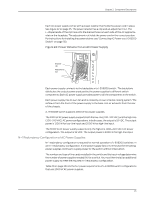
g020514 Chapter 2: Component Descriptions Figure 24: Fan Tray for a J-EX8208 Switch Fans Handle Spring-loaded latch The fan tray can be removed and replaced from the front of the chassis. The switch continues to operate for a limited time (2 minutes) during the replacement of the fan tray without thermal shutdown. CAUTION: You must replace the fan tray within 2 minutes of removing it. The air intake to cool the chassis is located on the right side of the chassis. Air is pulled into the chassis and is pushed thorough the line card cage towards the fan tray. Hot air exhausts from the left side of the chassis. See Figure 25 on page 40. 39
-
 1
1 -
2
-
3
-
4
-
5
-
6
-
7
-
8
-
9
-
10
-
11
-
12
-
13
-
14
-
15
-
16
-
17
-
18
-
19
-
20
-
21
-
22
-
23
-
24
-
25
-
26
-
27
-
28
-
29
-
30
-
31
-
32
-
33
-
34
-
35
-
36
-
37
-
38
-
39
-
40
-
41
-
42
-
43
-
44
-
45
-
46
-
47
-
48
-
49
-
 50
50 -
 51
51 -
 52
52 -
 53
53 -
 54
54 -
 55
55 -
 56
56 -
 57
57 -
 58
58 -
 59
59 -
 60
60 -
61
-
62
-
63
-
64
-
65
-
66
-
67
-
68
-
69
-
70
-
71
-
72
-
73
-
74
-
75
-
76
-
77
-
78
-
79
-
80
-
81
-
82
-
83
-
84
-
85
-
86
-
87
-
88
-
89
-
90
-
91
-
92
-
93
-
94
-
95
-
96
-
97
-
98
-
99
-
100
-
101
-
102
-
103
-
104
-
105
-
106
-
107
-
108
-
109
-
110
-
111
-
112
-
113
-
114
-
115
-
116
-
117
-
118
-
119
-
120
-
121
-
122
-
123
-
124
-
125
-
126
-
127
-
128
-
129
-
130
-
131
-
132
-
133
-
134
-
135
-
136
-
137
-
138
-
139
-
140
-
141
-
142
-
143
-
144
-
145
-
146
-
147
-
148
-
149
-
150
-
151
-
152
-
153
-
154
-
155
-
156
-
157
-
158
-
159
-
160
-
161
-
162
-
163
-
164
-
165
-
166
-
167
-
168
-
169
-
170
-
171
-
172
-
173
-
174
-
175
-
176
-
177
-
178
-
179
-
180
-
181
-
182
-
183
-
184
-
185
-
186
-
187
-
188
-
189
-
190
-
191
-
192
-
193
-
194
-
195
-
196
-
197
-
198
-
199
-
200
-
201
-
202
-
203
-
204
-
205
-
206
-
207
-
208
-
209
-
210
-
211
-
212
-
213
-
214
-
215
-
216
-
217
-
218
-
219
-
220
-
221
-
222
-
223
-
224
-
225
-
226
-
227
-
228
-
229
-
230
-
231
-
232
-
233
-
234
-
235
-
236
-
237
-
238
-
239
-
240
-
241
-
242
-
243
-
244
-
245
-
246
-
247
-
248
-
249
-
250
-
251
-
252
-
253
-
254
-
255
-
256
-
257
-
258
-
259
-
260
-
261
-
262
-
263
-
264
-
265
-
266
-
267
-
268
-
269
-
270
-
271
-
272
-
273
-
274
-
275
-
276
 |
 |
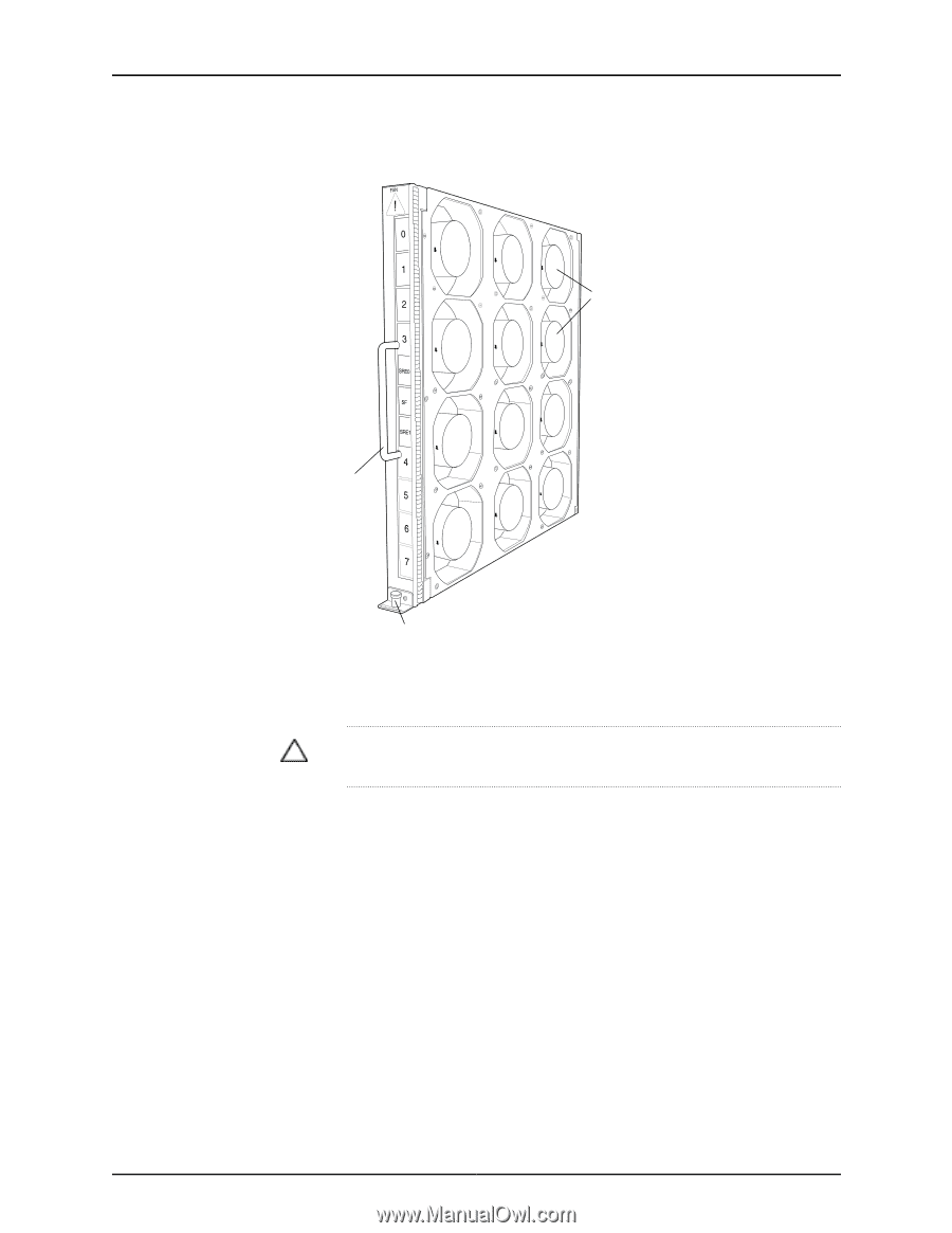
Figure 24: Fan Tray for a J-EX8208 Switch
g020514
Fans
Spring-loaded latch
Handle
The fan tray can be removed and replaced from the front of the chassis. The switch
continues to operate for a limited time (2 minutes) during the replacement of the fan
tray without thermal shutdown.
CAUTION:
You must replace the fan tray within 2 minutes of removing it.
The air intake to cool the chassis is located on the right side of the chassis. Air is pulled
into the chassis and is pushed thorough the line card cage towards the fan tray. Hot air
exhausts from the left side of the chassis. See Figure 25 on page 40.
39
Chapter 2: Component Descriptions