Dell PowerConnect J-8208 Hardware Guide - Page 54
Cooling System and Airflow in a J-EX8208 Switch, Table 22: Power Supply LEDs on J-EX8200 Switches
 |
View all Dell PowerConnect J-8208 manuals
Add to My Manuals
Save this manual to your list of manuals |
Page 54 highlights
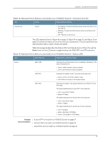
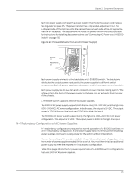
Dell PowerConnect J-Series J-EX8208 Ethernet Switch Hardware Guide Table 22: Power Supply LEDs on J-EX8200 Switches (continued) LED State Description OUTPUT OK Unlit Green Indicates one of the following: • DC output voltage is not within normal operating range. • Power supply is not supplying DC power correctly. • DC power output is within normal operating range. FAIL Yellow Unlit • Power supply has been disabled internally by the system. • Power supply is functioning normally. Yellow • On steadily-Power supply has failed. • Blinking-Demand for output power exceeds the supply. NOTE: If the INPUT OK LED and the OUTPUT OK LED are unlit, the AC power cord is not installed properly or the power supply has failed. If the INPUT OK LED is lit and the OUTPUT OK LED is unlit, the AC power supply is not installed properly or the power supply has an internal failure. If the FAIL LED is lit, the power supply has failed and must be replaced. If the FAIL LED is blinking, add a power supply to balance the power demand and supply. Related • AC Power Specifications for J-EX8200 Switches on page 75 Documentation • Power Requirements for J-EX8208 Switch Components on page 76 • AC Power Cord Specifications for a J-EX8200 Switch on page 76 • Connecting AC Power to a J-EX8200 Switch on page 130 Cooling System and Airflow in a J-EX8208 Switch The cooling system in a J-EX8208 switch consists of a single fan tray. The fan tray is a hot-insertable and hot-removable field-replaceable unit (FRU). The fan tray contains 12 fans. The fan tray installs vertically on the left side on the front of the chassis and provides side-to-side chassis cooling. A handle on the front faceplate facilitates handling of the fan tray. See Figure 24 on page 39. 38
-
 1
1 -
2
-
3
-
4
-
5
-
6
-
7
-
8
-
9
-
10
-
11
-
12
-
13
-
14
-
15
-
16
-
17
-
18
-
19
-
20
-
21
-
22
-
23
-
24
-
25
-
26
-
27
-
28
-
29
-
30
-
31
-
32
-
33
-
34
-
35
-
36
-
37
-
38
-
39
-
40
-
41
-
42
-
43
-
44
-
45
-
46
-
47
-
48
-
 49
49 -
 50
50 -
 51
51 -
 52
52 -
 53
53 -
 54
54 -
 55
55 -
 56
56 -
 57
57 -
 58
58 -
 59
59 -
60
-
61
-
62
-
63
-
64
-
65
-
66
-
67
-
68
-
69
-
70
-
71
-
72
-
73
-
74
-
75
-
76
-
77
-
78
-
79
-
80
-
81
-
82
-
83
-
84
-
85
-
86
-
87
-
88
-
89
-
90
-
91
-
92
-
93
-
94
-
95
-
96
-
97
-
98
-
99
-
100
-
101
-
102
-
103
-
104
-
105
-
106
-
107
-
108
-
109
-
110
-
111
-
112
-
113
-
114
-
115
-
116
-
117
-
118
-
119
-
120
-
121
-
122
-
123
-
124
-
125
-
126
-
127
-
128
-
129
-
130
-
131
-
132
-
133
-
134
-
135
-
136
-
137
-
138
-
139
-
140
-
141
-
142
-
143
-
144
-
145
-
146
-
147
-
148
-
149
-
150
-
151
-
152
-
153
-
154
-
155
-
156
-
157
-
158
-
159
-
160
-
161
-
162
-
163
-
164
-
165
-
166
-
167
-
168
-
169
-
170
-
171
-
172
-
173
-
174
-
175
-
176
-
177
-
178
-
179
-
180
-
181
-
182
-
183
-
184
-
185
-
186
-
187
-
188
-
189
-
190
-
191
-
192
-
193
-
194
-
195
-
196
-
197
-
198
-
199
-
200
-
201
-
202
-
203
-
204
-
205
-
206
-
207
-
208
-
209
-
210
-
211
-
212
-
213
-
214
-
215
-
216
-
217
-
218
-
219
-
220
-
221
-
222
-
223
-
224
-
225
-
226
-
227
-
228
-
229
-
230
-
231
-
232
-
233
-
234
-
235
-
236
-
237
-
238
-
239
-
240
-
241
-
242
-
243
-
244
-
245
-
246
-
247
-
248
-
249
-
250
-
251
-
252
-
253
-
254
-
255
-
256
-
257
-
258
-
259
-
260
-
261
-
262
-
263
-
264
-
265
-
266
-
267
-
268
-
269
-
270
-
271
-
272
-
273
-
274
-
275
-
276
 |
 |
