Dell PowerConnect J-8208 Hardware Guide - Page 112
Installing a Round-Hole Cage Nut Clip Nut
 |
View all Dell PowerConnect J-8208 manuals
Add to My Manuals
Save this manual to your list of manuals |
Page 112 highlights
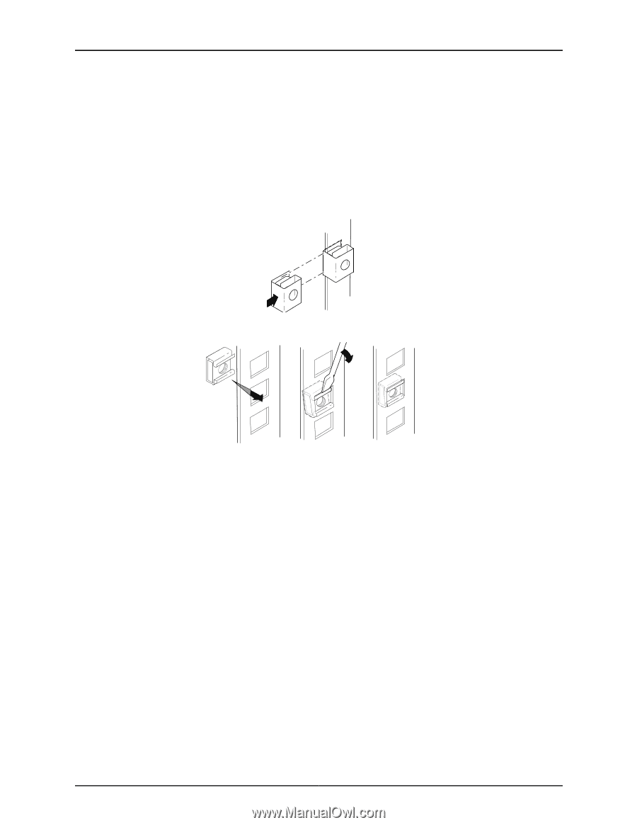
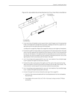
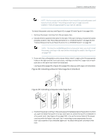
g040637 g040639 Dell PowerConnect J-Series J-EX8208 Ethernet Switch Hardware Guide page 63 and "Cabinet Requirements and Specifications for a J-EX8208 Switch" on page 66. 3. If your rack has unthreaded round or square holes, install 8 cage nuts in the appropriate holes on the left front and left rear rack posts, making sure that the 4 cage nuts on each post are on the same rack level front and back. Use Figure 34 on page 96 or Figure 35 on page 96 to help you with cage-nut installation. Figure 34: Installing a Round-Hole Cage Nut (Clip Nut) Figure 35: Installing a Square-Hole Cage Nut 4. Position the left front adjustable mounting bracket at the desired position in the left side of the rack and line up its front screw holes with the holes in the rack. 5. Use 4 mounting screws appropriate for your rack-plus washers if you installed cage nuts-to attach the left front bracket to the rack. 6. Position one of the rear brackets at the left rear of the rack on the same level as the left front bracket, so that the rear bracket overlaps with the left front bracket. The screw holes for connecting the front and rear brackets should overlap. 7. Use 4 mounting screws appropriate for your rack-plus washers if you installed cage nuts-to attach the left rear bracket to the rack. 8. Connect left front and rear brackets (see Figure 36 on page 97): a. Insert 6 of the screws provided with the mounting brackets into the overlapping bracket holes. b. Hand tighten the screws fully (to 12-16 in.-lb torque) using a number 2 Phillips screwdriver. 96
-
 1
1 -
2
-
3
-
4
-
5
-
6
-
7
-
8
-
9
-
10
-
11
-
12
-
13
-
14
-
15
-
16
-
17
-
18
-
19
-
20
-
21
-
22
-
23
-
24
-
25
-
26
-
27
-
28
-
29
-
30
-
31
-
32
-
33
-
34
-
35
-
36
-
37
-
38
-
39
-
40
-
41
-
42
-
43
-
44
-
45
-
46
-
47
-
48
-
49
-
50
-
51
-
52
-
53
-
54
-
55
-
56
-
57
-
58
-
59
-
60
-
61
-
62
-
63
-
64
-
65
-
66
-
67
-
68
-
69
-
70
-
71
-
72
-
73
-
74
-
75
-
76
-
77
-
78
-
79
-
80
-
81
-
82
-
83
-
84
-
85
-
86
-
87
-
88
-
89
-
90
-
91
-
92
-
93
-
94
-
95
-
96
-
97
-
98
-
99
-
100
-
101
-
102
-
103
-
104
-
105
-
106
-
 107
107 -
 108
108 -
 109
109 -
 110
110 -
 111
111 -
 112
112 -
 113
113 -
 114
114 -
 115
115 -
 116
116 -
 117
117 -
118
-
119
-
120
-
121
-
122
-
123
-
124
-
125
-
126
-
127
-
128
-
129
-
130
-
131
-
132
-
133
-
134
-
135
-
136
-
137
-
138
-
139
-
140
-
141
-
142
-
143
-
144
-
145
-
146
-
147
-
148
-
149
-
150
-
151
-
152
-
153
-
154
-
155
-
156
-
157
-
158
-
159
-
160
-
161
-
162
-
163
-
164
-
165
-
166
-
167
-
168
-
169
-
170
-
171
-
172
-
173
-
174
-
175
-
176
-
177
-
178
-
179
-
180
-
181
-
182
-
183
-
184
-
185
-
186
-
187
-
188
-
189
-
190
-
191
-
192
-
193
-
194
-
195
-
196
-
197
-
198
-
199
-
200
-
201
-
202
-
203
-
204
-
205
-
206
-
207
-
208
-
209
-
210
-
211
-
212
-
213
-
214
-
215
-
216
-
217
-
218
-
219
-
220
-
221
-
222
-
223
-
224
-
225
-
226
-
227
-
228
-
229
-
230
-
231
-
232
-
233
-
234
-
235
-
236
-
237
-
238
-
239
-
240
-
241
-
242
-
243
-
244
-
245
-
246
-
247
-
248
-
249
-
250
-
251
-
252
-
253
-
254
-
255
-
256
-
257
-
258
-
259
-
260
-
261
-
262
-
263
-
264
-
265
-
266
-
267
-
268
-
269
-
270
-
271
-
272
-
273
-
274
-
275
-
276
 |
 |