HP P Class 450/500/550/600/650/700/750 HP Visualize x- and p-Class (733,800, 8 - Page 128
Installing and Removing a Voltage Regulator, Module VRM
 |
View all HP P Class 450/500/550/600/650/700/750 manuals
Add to My Manuals
Save this manual to your list of manuals |
Page 128 highlights
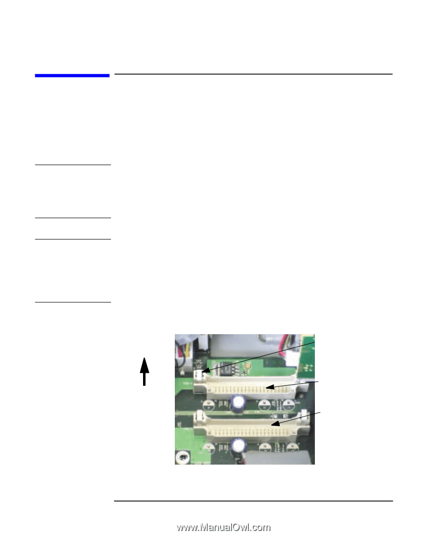
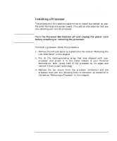
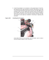
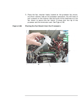
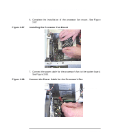
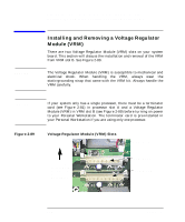
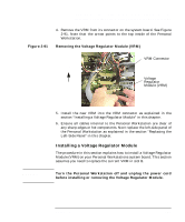
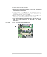
Opening Your Personal Workstation and Installing Accessories Installing and Removing a Voltage Regulator Module (VRM) CAUTION Installing and Removing a Voltage Regulator Module (VRM) There are two Voltage Regulator Module (VRM) slots on your system board. This section will discuss the installation and removal of the VRM from VRM slot B. See Figure 2-89. The Voltage Regulator Module (VRM) is susceptible to mechanical and electrical shock. When handling the VRM, always wear the static-grounding strap that came with the VRM kit. Always handle the VRM carefully. CAUTION Figure 2-89 If your system only has a single processor, there must be a terminator card (see Figure 2-81) in processor slot A and a Voltage Regulator Module (VRM) in VRM slot B (see Figure 2-89) before turning on power to your Personal Workstation. The terminator card is pre-installed in your Personal Workstation if you are using only one processor. Voltage Regulator Module (VRM) Slots Ejector Tab This arrow point toward the top of the Personal Workstation VRM Slot A VRM Slot B 128 Chapter 2
-
 1
1 -
2
-
3
-
4
-
5
-
6
-
7
-
8
-
9
-
10
-
11
-
12
-
13
-
14
-
15
-
16
-
17
-
18
-
19
-
20
-
21
-
22
-
23
-
24
-
25
-
26
-
27
-
28
-
29
-
30
-
31
-
32
-
33
-
34
-
35
-
36
-
37
-
38
-
39
-
40
-
41
-
42
-
43
-
44
-
45
-
46
-
47
-
48
-
49
-
50
-
51
-
52
-
53
-
54
-
55
-
56
-
57
-
58
-
59
-
60
-
61
-
62
-
63
-
64
-
65
-
66
-
67
-
68
-
69
-
70
-
71
-
72
-
73
-
74
-
75
-
76
-
77
-
78
-
79
-
80
-
81
-
82
-
83
-
84
-
85
-
86
-
87
-
88
-
89
-
90
-
91
-
92
-
93
-
94
-
95
-
96
-
97
-
98
-
99
-
100
-
101
-
102
-
103
-
104
-
105
-
106
-
107
-
108
-
109
-
110
-
111
-
112
-
113
-
114
-
115
-
116
-
117
-
118
-
119
-
120
-
121
-
122
-
 123
123 -
 124
124 -
 125
125 -
 126
126 -
 127
127 -
 128
128 -
 129
129 -
 130
130 -
 131
131 -
 132
132 -
 133
133 -
134
-
135
-
136
-
137
-
138
-
139
-
140
-
141
-
142
-
143
-
144
-
145
-
146
-
147
-
148
-
149
-
150
-
151
-
152
-
153
-
154
-
155
-
156
-
157
-
158
-
159
-
160
-
161
-
162
-
163
-
164
-
165
-
166
-
167
-
168
-
169
-
170
-
171
-
172
-
173
-
174
-
175
-
176
-
177
-
178
-
179
-
180
-
181
-
182
-
183
-
184
-
185
-
186
-
187
-
188
-
189
-
190
-
191
-
192
-
193
-
194
-
195
 |
 |