HP P Class 450/500/550/600/650/700/750 HP Visualize x- and p-Class (733,800, 8 - Page 82
Attaching the Guide Rail to the CD Drive, Properly Installed Guide Rail
 |
View all HP P Class 450/500/550/600/650/700/750 manuals
Add to My Manuals
Save this manual to your list of manuals |
Page 82 highlights
NOTE Opening Your Personal Workstation and Installing Accessories Removable Media Devices 3. Attach the guide rails to both sides of the CD Drive. The pins of the guide rail should be placed in the lower holes on the side of the CD drive. See Figure 2-32 and Figure 2-33. The CD drive guide rails are color coded black. They are located on the chassis of the CD drive bay area. Figure 2-32 Attaching the Guide Rail to the CD Drive CD Drive Top Lower Pin Hole Figure 2-33 Guide Rail Properly Installed Guide Rail CD Drive Front Retainer Pin CD Drive Top CD Drive Front Guide Rail 82 Ejector Tab (on both sides) Chapter 2
-
 1
1 -
2
-
3
-
4
-
5
-
6
-
7
-
8
-
9
-
10
-
11
-
12
-
13
-
14
-
15
-
16
-
17
-
18
-
19
-
20
-
21
-
22
-
23
-
24
-
25
-
26
-
27
-
28
-
29
-
30
-
31
-
32
-
33
-
34
-
35
-
36
-
37
-
38
-
39
-
40
-
41
-
42
-
43
-
44
-
45
-
46
-
47
-
48
-
49
-
50
-
51
-
52
-
53
-
54
-
55
-
56
-
57
-
58
-
59
-
60
-
61
-
62
-
63
-
64
-
65
-
66
-
67
-
68
-
69
-
70
-
71
-
72
-
73
-
74
-
75
-
76
-
 77
77 -
 78
78 -
 79
79 -
 80
80 -
 81
81 -
 82
82 -
 83
83 -
 84
84 -
 85
85 -
 86
86 -
 87
87 -
88
-
89
-
90
-
91
-
92
-
93
-
94
-
95
-
96
-
97
-
98
-
99
-
100
-
101
-
102
-
103
-
104
-
105
-
106
-
107
-
108
-
109
-
110
-
111
-
112
-
113
-
114
-
115
-
116
-
117
-
118
-
119
-
120
-
121
-
122
-
123
-
124
-
125
-
126
-
127
-
128
-
129
-
130
-
131
-
132
-
133
-
134
-
135
-
136
-
137
-
138
-
139
-
140
-
141
-
142
-
143
-
144
-
145
-
146
-
147
-
148
-
149
-
150
-
151
-
152
-
153
-
154
-
155
-
156
-
157
-
158
-
159
-
160
-
161
-
162
-
163
-
164
-
165
-
166
-
167
-
168
-
169
-
170
-
171
-
172
-
173
-
174
-
175
-
176
-
177
-
178
-
179
-
180
-
181
-
182
-
183
-
184
-
185
-
186
-
187
-
188
-
189
-
190
-
191
-
192
-
193
-
194
-
195
 |
 |
82
Chapter 2
Opening Your Personal Workstation and Installing Accessories
Removable Media Devices
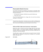
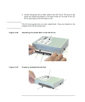
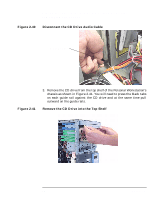
3.
Attach the guide rails to both sides of the CD Drive. The pins of the
guide rail should be placed in the lower holes on the side of the CD
drive. See Figure 2-32 and Figure 2-33.
NOTE
The CD drive guide rails are color coded black. They are located on the
chassis of the CD drive bay area.
Figure 2-32
Attaching the Guide Rail to the CD Drive
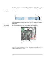
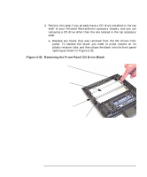
Figure 2-33
Properly Installed Guide Rail
CD Drive Top
CD Drive
Front
Lower Pin Hole
Retainer Pin
Guide Rail
CD Drive Top
CD Drive
Front
Guide Rail
Ejector Tab
(on both sides)