HP P Class 450/500/550/600/650/700/750 HP Visualize x- and p-Class (733,800, 8 - Page 131
Installing a Voltage Regulator Module
 |
View all HP P Class 450/500/550/600/650/700/750 manuals
Add to My Manuals
Save this manual to your list of manuals |
Page 131 highlights
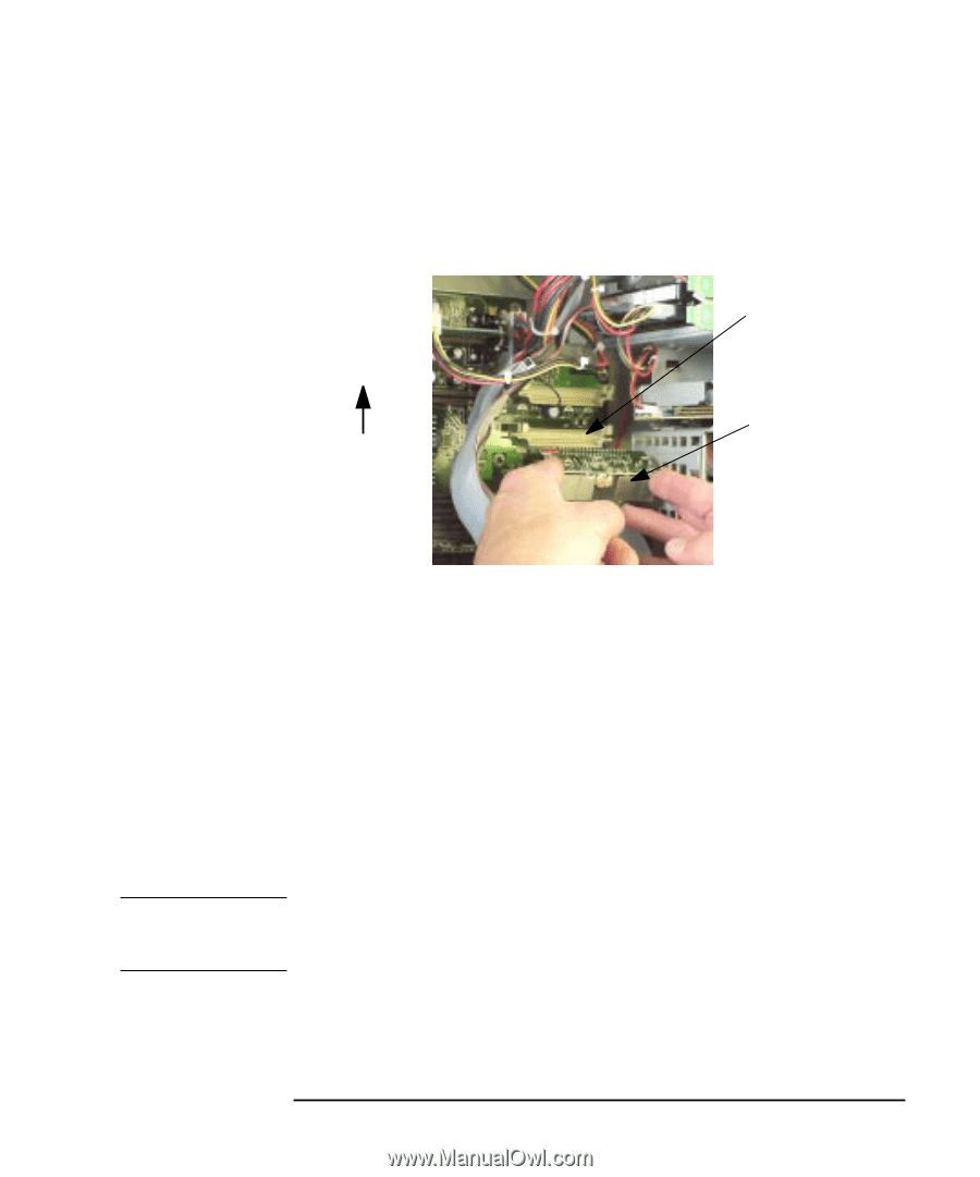
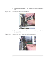
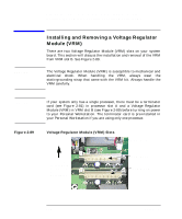
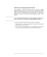
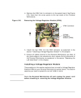
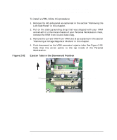
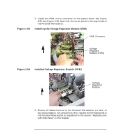
Opening Your Personal Workstation and Installing Accessories Installing and Removing a Voltage Regulator Module (VRM) Figure 2-91 4. Remove the VRM from its connector on the system board. See Figure 2-91. Note that the arrow points to the top inside of the Personal Workstation. Removing the Voltage Regulator Module (VRM) VRM Connector Top Voltage Regulator Module (VRM) WARNING 5. Install the new VRM into the VRM connector as explained in the section "Installing a Voltage Regulator Module" in this chapter. 6. Ensure all cables internal to the Personal Workstation are clear of any sharp edges or hot components. Next replace the left-side panel of the Personal Workstation as explained in the section "Replacing the Left-Side Panel" in this chapter. Installing a Voltage Regulator Module The procedure in this section explains how to install a Voltage Regulator Module (VRM) on your Personal Workstations system board. This section assumes you need to replace the current VRM in slot B. Turn the Personal Workstation off and unplug the power cord before installing or removing the Voltage Regulator Module. Chapter 2 131
-
 1
1 -
2
-
3
-
4
-
5
-
6
-
7
-
8
-
9
-
10
-
11
-
12
-
13
-
14
-
15
-
16
-
17
-
18
-
19
-
20
-
21
-
22
-
23
-
24
-
25
-
26
-
27
-
28
-
29
-
30
-
31
-
32
-
33
-
34
-
35
-
36
-
37
-
38
-
39
-
40
-
41
-
42
-
43
-
44
-
45
-
46
-
47
-
48
-
49
-
50
-
51
-
52
-
53
-
54
-
55
-
56
-
57
-
58
-
59
-
60
-
61
-
62
-
63
-
64
-
65
-
66
-
67
-
68
-
69
-
70
-
71
-
72
-
73
-
74
-
75
-
76
-
77
-
78
-
79
-
80
-
81
-
82
-
83
-
84
-
85
-
86
-
87
-
88
-
89
-
90
-
91
-
92
-
93
-
94
-
95
-
96
-
97
-
98
-
99
-
100
-
101
-
102
-
103
-
104
-
105
-
106
-
107
-
108
-
109
-
110
-
111
-
112
-
113
-
114
-
115
-
116
-
117
-
118
-
119
-
120
-
121
-
122
-
123
-
124
-
125
-
 126
126 -
 127
127 -
 128
128 -
 129
129 -
 130
130 -
 131
131 -
 132
132 -
 133
133 -
 134
134 -
 135
135 -
 136
136 -
137
-
138
-
139
-
140
-
141
-
142
-
143
-
144
-
145
-
146
-
147
-
148
-
149
-
150
-
151
-
152
-
153
-
154
-
155
-
156
-
157
-
158
-
159
-
160
-
161
-
162
-
163
-
164
-
165
-
166
-
167
-
168
-
169
-
170
-
171
-
172
-
173
-
174
-
175
-
176
-
177
-
178
-
179
-
180
-
181
-
182
-
183
-
184
-
185
-
186
-
187
-
188
-
189
-
190
-
191
-
192
-
193
-
194
-
195
 |
 |