HP P Class 450/500/550/600/650/700/750 HP Visualize x- and p-Class (733,800, 8 - Page 74
Installed DIMM Card, Keyed DIMM Card
 |
View all HP P Class 450/500/550/600/650/700/750 manuals
Add to My Manuals
Save this manual to your list of manuals |
Page 74 highlights
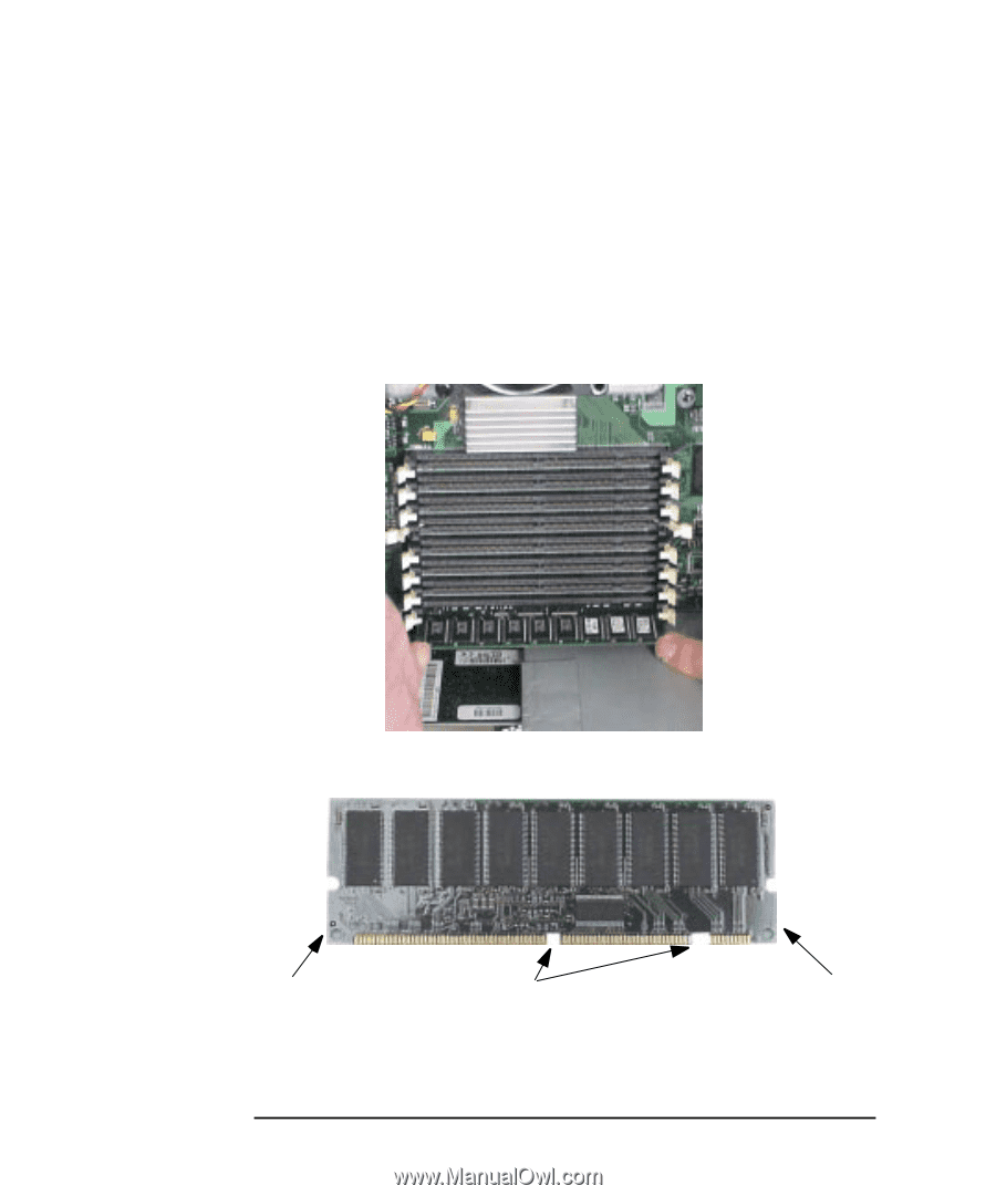
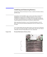
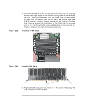
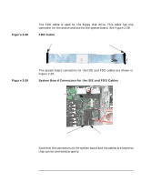
Opening Your Personal Workstation and Installing Accessories Installing and Removing Memory Figure 2-23 4. Insert the DIMM card into its appropriate memory slots by aligning the left and right edges of the card with the guides on the memory card slot. Then push downward until the DIMM card is firmly seated in place, and the ejector tabs lock in place. See Figure 2-24. The DIMM cards are keyed for proper installation. See Figure 2-23. Note that this step showed the installation of the DIMM card in memory slot 1A. Its matching DIMM card would be place in memory slot 1B. Figure 2-23 shows the eight X-Class memory slots. Installed DIMM Card Figure 2-24 Keyed DIMM Card Left edge Keys Right Edge 5. Replace the left-side panel as explained in the section "Replacing the Left-Side Panel" in this chapter. 74 Chapter 2
-
 1
1 -
2
-
3
-
4
-
5
-
6
-
7
-
8
-
9
-
10
-
11
-
12
-
13
-
14
-
15
-
16
-
17
-
18
-
19
-
20
-
21
-
22
-
23
-
24
-
25
-
26
-
27
-
28
-
29
-
30
-
31
-
32
-
33
-
34
-
35
-
36
-
37
-
38
-
39
-
40
-
41
-
42
-
43
-
44
-
45
-
46
-
47
-
48
-
49
-
50
-
51
-
52
-
53
-
54
-
55
-
56
-
57
-
58
-
59
-
60
-
61
-
62
-
63
-
64
-
65
-
66
-
67
-
68
-
 69
69 -
 70
70 -
 71
71 -
 72
72 -
 73
73 -
 74
74 -
 75
75 -
 76
76 -
 77
77 -
 78
78 -
 79
79 -
80
-
81
-
82
-
83
-
84
-
85
-
86
-
87
-
88
-
89
-
90
-
91
-
92
-
93
-
94
-
95
-
96
-
97
-
98
-
99
-
100
-
101
-
102
-
103
-
104
-
105
-
106
-
107
-
108
-
109
-
110
-
111
-
112
-
113
-
114
-
115
-
116
-
117
-
118
-
119
-
120
-
121
-
122
-
123
-
124
-
125
-
126
-
127
-
128
-
129
-
130
-
131
-
132
-
133
-
134
-
135
-
136
-
137
-
138
-
139
-
140
-
141
-
142
-
143
-
144
-
145
-
146
-
147
-
148
-
149
-
150
-
151
-
152
-
153
-
154
-
155
-
156
-
157
-
158
-
159
-
160
-
161
-
162
-
163
-
164
-
165
-
166
-
167
-
168
-
169
-
170
-
171
-
172
-
173
-
174
-
175
-
176
-
177
-
178
-
179
-
180
-
181
-
182
-
183
-
184
-
185
-
186
-
187
-
188
-
189
-
190
-
191
-
192
-
193
-
194
-
195
 |
 |