Intermec PX4i PX4i and PX6i High Performance Printer User's Manual - Page 134
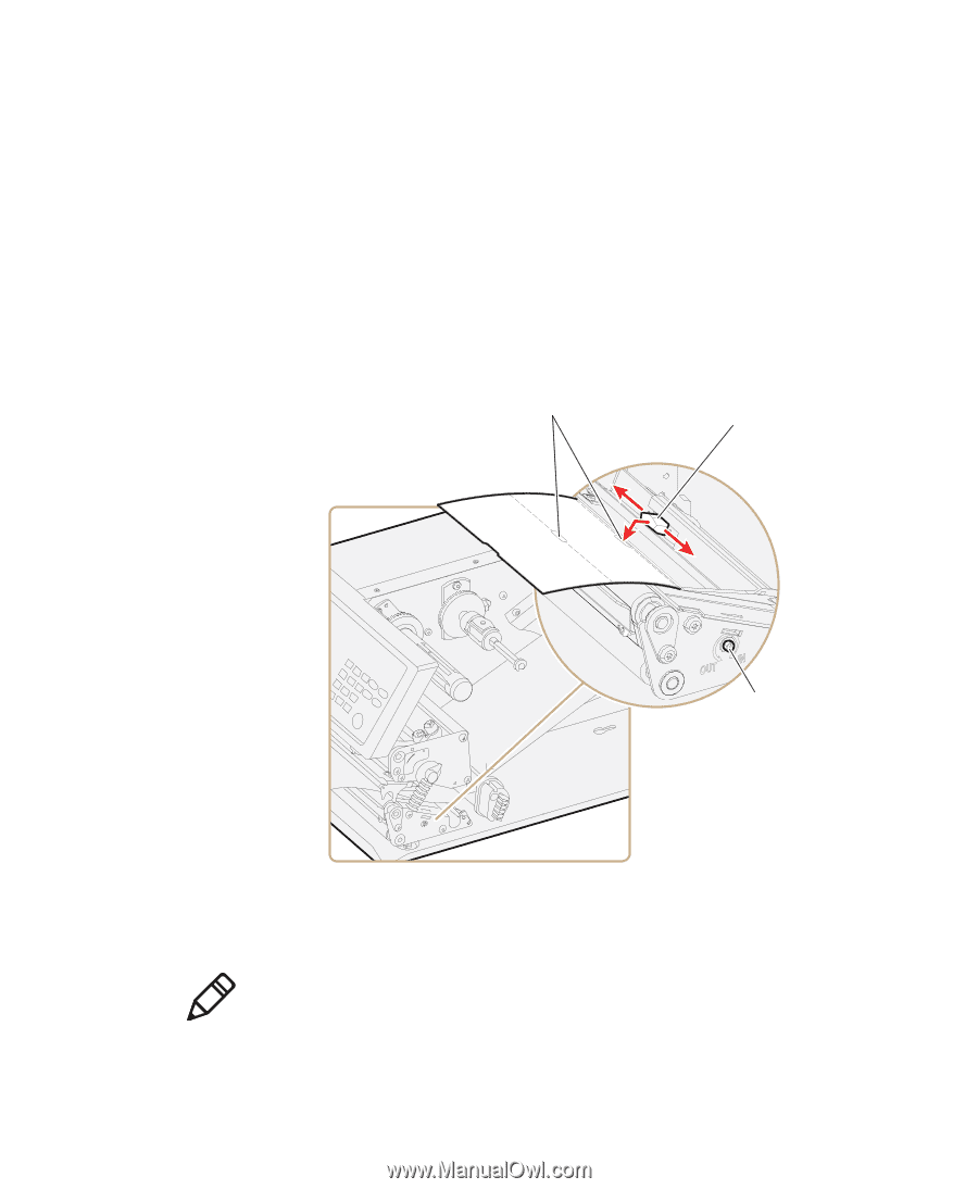
To adjust the LSS, lifted to make sure that the point of detection on the upper sensor
 |
View all Intermec PX4i manuals
Add to My Manuals
Save this manual to your list of manuals |
Page 134 highlights
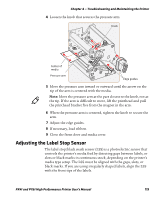
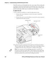
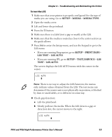
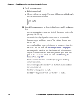
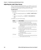
Chapter 4 - Troubleshooting and Maintaining the Printer The LSS can be moved laterally from the inner edge of the media path to 50 mm (1.96 in) outward, which corresponds to the center line of full width media. One part of the sensor is on the upper media guide and the other part of the sensor is under the lower guide. To adjust the LSS 1 Use a slotted screwdriver to turn the adjustment screw. • Rotate the screw clockwise to move the sensor toward the center section. • Rotate the screw counterclockwise to move the sensor outward, away from the center section. Detection slots Upper part of LSS Adjustment screw 2 Look at the print mechanism from the front with the printhead lifted to make sure that the point of detection on the upper sensor is aligned with the center of the slots or marks in the media. Note: You can also use the markings, spaced at 1 cm (0.39 in) intervals, on the lower guide plate. This method can be especially useful for black marks. Be sure to measure the lateral position of the black marks with a ruler before loading the media. 120 PX4i and PX6i High Performance Printer User's Manual
-
 1
1 -
2
-
3
-
4
-
5
-
6
-
7
-
8
-
9
-
10
-
11
-
12
-
13
-
14
-
15
-
16
-
17
-
18
-
19
-
20
-
21
-
22
-
23
-
24
-
25
-
26
-
27
-
28
-
29
-
30
-
31
-
32
-
33
-
34
-
35
-
36
-
37
-
38
-
39
-
40
-
41
-
42
-
43
-
44
-
45
-
46
-
47
-
48
-
49
-
50
-
51
-
52
-
53
-
54
-
55
-
56
-
57
-
58
-
59
-
60
-
61
-
62
-
63
-
64
-
65
-
66
-
67
-
68
-
69
-
70
-
71
-
72
-
73
-
74
-
75
-
76
-
77
-
78
-
79
-
80
-
81
-
82
-
83
-
84
-
85
-
86
-
87
-
88
-
89
-
90
-
91
-
92
-
93
-
94
-
95
-
96
-
97
-
98
-
99
-
100
-
101
-
102
-
103
-
104
-
105
-
106
-
107
-
108
-
109
-
110
-
111
-
112
-
113
-
114
-
115
-
116
-
117
-
118
-
119
-
120
-
121
-
122
-
123
-
124
-
125
-
126
-
127
-
128
-
 129
129 -
 130
130 -
 131
131 -
 132
132 -
 133
133 -
 134
134 -
 135
135 -
 136
136 -
 137
137 -
 138
138 -
 139
139 -
140
-
141
-
142
-
143
-
144
-
145
-
146
-
147
-
148
-
149
-
150
-
151
-
152
-
153
-
154
-
155
-
156
-
157
-
158
-
159
-
160
-
161
-
162
-
163
-
164
-
165
-
166
-
167
-
168
-
169
-
170
-
171
-
172
-
173
-
174
-
175
-
176
-
177
-
178
-
179
-
180
-
181
-
182
-
183
-
184
-
185
-
186
-
187
-
188
-
189
-
190
-
191
-
192
-
193
-
194
-
195
-
196
-
197
-
198
-
199
-
200
-
201
-
202
-
203
-
204
 |
 |