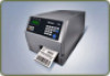
Intermec PX4i PX4i and PX6i High Performance Printer User's Manual - Page 157
Parallel IEEE 1284 Interface, Understanding the Ethernet LEDs
 |
View all Intermec PX4i manuals
Add to My Manuals
Save this manual to your list of manuals |
Page 157 highlights
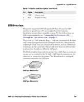
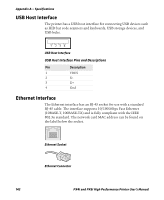
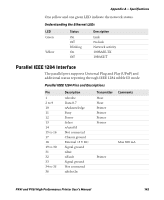
Appendix A - Specifications One yellow and one green LED indicate the network status. Understanding the Ethernet LEDs LED Green Yellow Status On Off Blinking On Off Description Link No link Network activity 100BASE-TX 10BASE-T Parallel IEEE 1284 Interface The parallel port supports Universal Plug and Play (UPnP) and additional status reporting through IEEE 1284 nibble ID mode. Parallel IEEE 1284 Pins and Descriptions Pin 1 2 to 9 10 11 12 13 14 15 to 16 17 18 19 to 30 31 32 33 34 to 35 36 Description nStrobe Data 0-7 nAcknowledge Busy Perror Select nAutoFd Not connected Chassis ground External +5 V DC Signal ground nInit nFault Signal ground Not connected nSelectIn Transmitter Host Host Printer Printer Printer Printer Comments Max 500 mA Printer PX4i and PX6i High Performance Printer User's Manual 143
-
 1
1 -
2
-
3
-
4
-
5
-
6
-
7
-
8
-
9
-
10
-
11
-
12
-
13
-
14
-
15
-
16
-
17
-
18
-
19
-
20
-
21
-
22
-
23
-
24
-
25
-
26
-
27
-
28
-
29
-
30
-
31
-
32
-
33
-
34
-
35
-
36
-
37
-
38
-
39
-
40
-
41
-
42
-
43
-
44
-
45
-
46
-
47
-
48
-
49
-
50
-
51
-
52
-
53
-
54
-
55
-
56
-
57
-
58
-
59
-
60
-
61
-
62
-
63
-
64
-
65
-
66
-
67
-
68
-
69
-
70
-
71
-
72
-
73
-
74
-
75
-
76
-
77
-
78
-
79
-
80
-
81
-
82
-
83
-
84
-
85
-
86
-
87
-
88
-
89
-
90
-
91
-
92
-
93
-
94
-
95
-
96
-
97
-
98
-
99
-
100
-
101
-
102
-
103
-
104
-
105
-
106
-
107
-
108
-
109
-
110
-
111
-
112
-
113
-
114
-
115
-
116
-
117
-
118
-
119
-
120
-
121
-
122
-
123
-
124
-
125
-
126
-
127
-
128
-
129
-
130
-
131
-
132
-
133
-
134
-
135
-
136
-
137
-
138
-
139
-
140
-
141
-
142
-
143
-
144
-
145
-
146
-
147
-
148
-
149
-
150
-
151
-
 152
152 -
 153
153 -
 154
154 -
 155
155 -
 156
156 -
 157
157 -
 158
158 -
 159
159 -
 160
160 -
 161
161 -
 162
162 -
163
-
164
-
165
-
166
-
167
-
168
-
169
-
170
-
171
-
172
-
173
-
174
-
175
-
176
-
177
-
178
-
179
-
180
-
181
-
182
-
183
-
184
-
185
-
186
-
187
-
188
-
189
-
190
-
191
-
192
-
193
-
194
-
195
-
196
-
197
-
198
-
199
-
200
-
201
-
202
-
203
-
204
 |
 |