HP Dc5700 HP Compaq dc5700 Business PC Service Reference Guide, 1st Edition - Page 111
Cable Designator, Cable
 |
UPC - 882780819535
View all HP Dc5700 manuals
Add to My Manuals
Save this manual to your list of manuals |
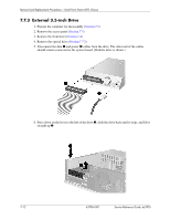
Page 111 highlights
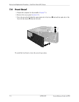
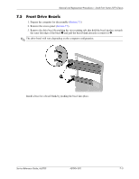
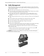
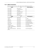
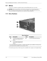
Removal and Replacement Procedures- Small Form Factor (SFF) Chassis 7.6.1 Cable Connections System board connectors are color-coded to make it easier to find the proper connection. Cable To Cable Designator Power Supply Main power, P1 P1 Power Supply 1st SATA Hard drive P2 Power Supply CPU power P3 Power Supply 2nd SATA Hard drive P4 Power Supply SATA Optical drive P6 Power Supply Diskette drive P7 Power Supply SATA Optical drive P6 Cable To PCA Designator Front LED/Power System board P5 Speaker System board P6, SPKR Chassis fan System board P8, F CHASSIS FAN Diskette drive System board P10, FLOPPY (Black) Front audio System board P23, FRNT AUD, (Blue) Front I/O USB System board P24, FRONT USB (Yellow) Serial port B System board P52, COM B 1st SATA Hard drive System board P60, SATA0 (Dark Blue) 1st ODD or 2nd SATA Hard drive if no ODD System board P61, SATA1 (White) ODD if 2nd SATA Hard drive System board present P62, SATA4 (Light blue) Service Reference Guide, dc5700 437804-001 7-7
-
 1
1 -
2
-
3
-
4
-
5
-
6
-
7
-
8
-
9
-
10
-
11
-
12
-
13
-
14
-
15
-
16
-
17
-
18
-
19
-
20
-
21
-
22
-
23
-
24
-
25
-
26
-
27
-
28
-
29
-
30
-
31
-
32
-
33
-
34
-
35
-
36
-
37
-
38
-
39
-
40
-
41
-
42
-
43
-
44
-
45
-
46
-
47
-
48
-
49
-
50
-
51
-
52
-
53
-
54
-
55
-
56
-
57
-
58
-
59
-
60
-
61
-
62
-
63
-
64
-
65
-
66
-
67
-
68
-
69
-
70
-
71
-
72
-
73
-
74
-
75
-
76
-
77
-
78
-
79
-
80
-
81
-
82
-
83
-
84
-
85
-
86
-
87
-
88
-
89
-
90
-
91
-
92
-
93
-
94
-
95
-
96
-
97
-
98
-
99
-
100
-
101
-
102
-
103
-
104
-
105
-
 106
106 -
 107
107 -
 108
108 -
 109
109 -
 110
110 -
 111
111 -
 112
112 -
 113
113 -
 114
114 -
 115
115 -
 116
116 -
117
-
118
-
119
-
120
-
121
-
122
-
123
-
124
-
125
-
126
-
127
-
128
-
129
-
130
-
131
-
132
-
133
-
134
-
135
-
136
-
137
-
138
-
139
-
140
-
141
-
142
-
143
-
144
-
145
-
146
-
147
-
148
-
149
-
150
-
151
-
152
-
153
-
154
-
155
-
156
-
157
-
158
-
159
-
160
-
161
-
162
-
163
-
164
-
165
-
166
-
167
-
168
-
169
-
170
-
171
-
172
-
173
-
174
-
175
-
176
-
177
-
178
-
179
-
180
-
181
-
182
-
183
-
184
-
185
-
186
-
187
-
188
-
189
-
190
-
191
-
192
-
193
-
194
-
195
-
196
-
197
-
198
-
199
-
200
-
201
-
202
-
203
-
204
-
205
-
206
-
207
-
208
-
209
-
210
-
211
-
212
-
213
-
214
-
215
-
216
 |
 |