HP Dc5700 HP Compaq dc5700 Business PC Service Reference Guide, 1st Edition - Page 88
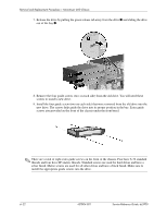
There are a total of eight extra guide screws on the front of the chassis. Four have 6-32 standard
 |
UPC - 882780819535
View all HP Dc5700 manuals
Add to My Manuals
Save this manual to your list of manuals |
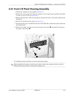
Page 88 highlights
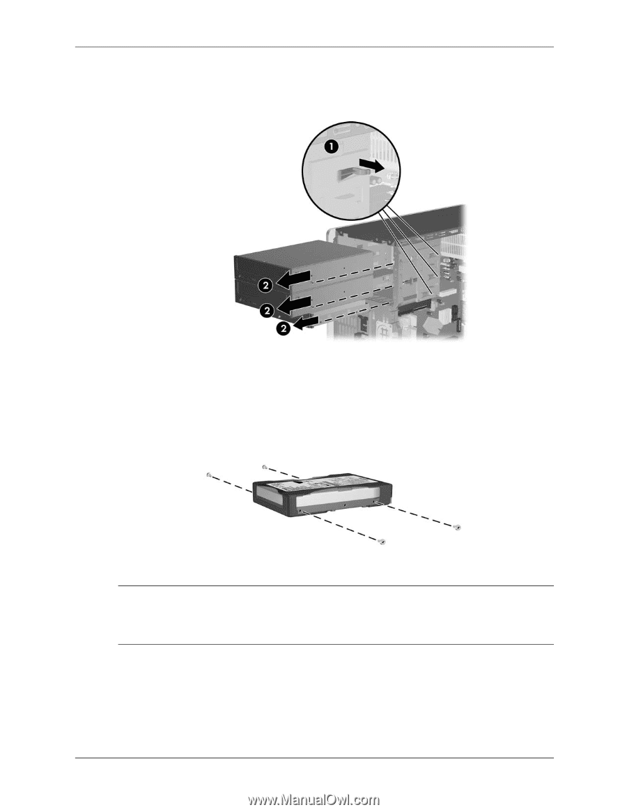
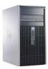
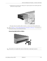
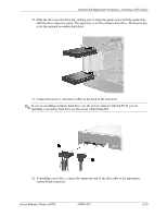
Removal and Replacement Procedures- Microtower (MT) Chassis 7. Release the drive by pulling the green release tab away from the drive 1 and sliding the drive out of the bay 2. 8. Remove the four guide screws (two on each side) from the old drive. You will need these screws to install a new drive. 9. Install the four guide screw (two on each side) that were removed from the old drive into the new drive. The screws help guide the drive into its proper position in the bay. Extra guide screws atre provided on the front of the chassis under the front bezel. ✎ There are a total of eight extra guide screws on the front of the chassis. Four have 6-32 standard threads and four have M3 metric threads. Standard screws are used for hard drives and have a silver finish. Metric screws are used for all other drives and have a black finish. Make sure to install the appropriate guide screws into the drive. 6-22 437804-001 Service Reference Guide, dc5700
-
 1
1 -
2
-
3
-
4
-
5
-
6
-
7
-
8
-
9
-
10
-
11
-
12
-
13
-
14
-
15
-
16
-
17
-
18
-
19
-
20
-
21
-
22
-
23
-
24
-
25
-
26
-
27
-
28
-
29
-
30
-
31
-
32
-
33
-
34
-
35
-
36
-
37
-
38
-
39
-
40
-
41
-
42
-
43
-
44
-
45
-
46
-
47
-
48
-
49
-
50
-
51
-
52
-
53
-
54
-
55
-
56
-
57
-
58
-
59
-
60
-
61
-
62
-
63
-
64
-
65
-
66
-
67
-
68
-
69
-
70
-
71
-
72
-
73
-
74
-
75
-
76
-
77
-
78
-
79
-
80
-
81
-
82
-
 83
83 -
 84
84 -
 85
85 -
 86
86 -
 87
87 -
 88
88 -
 89
89 -
 90
90 -
 91
91 -
 92
92 -
 93
93 -
94
-
95
-
96
-
97
-
98
-
99
-
100
-
101
-
102
-
103
-
104
-
105
-
106
-
107
-
108
-
109
-
110
-
111
-
112
-
113
-
114
-
115
-
116
-
117
-
118
-
119
-
120
-
121
-
122
-
123
-
124
-
125
-
126
-
127
-
128
-
129
-
130
-
131
-
132
-
133
-
134
-
135
-
136
-
137
-
138
-
139
-
140
-
141
-
142
-
143
-
144
-
145
-
146
-
147
-
148
-
149
-
150
-
151
-
152
-
153
-
154
-
155
-
156
-
157
-
158
-
159
-
160
-
161
-
162
-
163
-
164
-
165
-
166
-
167
-
168
-
169
-
170
-
171
-
172
-
173
-
174
-
175
-
176
-
177
-
178
-
179
-
180
-
181
-
182
-
183
-
184
-
185
-
186
-
187
-
188
-
189
-
190
-
191
-
192
-
193
-
194
-
195
-
196
-
197
-
198
-
199
-
200
-
201
-
202
-
203
-
204
-
205
-
206
-
207
-
208
-
209
-
210
-
211
-
212
-
213
-
214
-
215
-
216
 |
 |