HP Dc5700 HP Compaq dc5700 Business PC Service Reference Guide, 1st Edition - Page 211
Index - sff specifications
 |
UPC - 882780819535
View all HP Dc5700 manuals
Add to My Manuals
Save this manual to your list of manuals |
Page 211 highlights
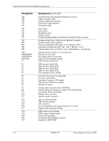
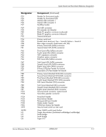
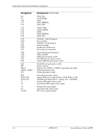
Index 24-pin power pin assignments A-5 6-pin power pin assignments A-6 A access panel MT removal and replacement 6-4 access panel, SFF removal and replacement 7-3 Active Management Technology (Intel) 3-7 adding devices 1-1 Altiris Deployment Solution Agent 3-2 asset tracking 3-16 ATA/ATAPI (IDE) drive cable pin assignments A-5 B Backup and Recovery Manager 1-2 battery disposal 5-9 MT removal and replacement 6-34 to 6-37 SFF removal and replacement 7-32 to 7-35 BIOS, ROM flash 3-9 blank screen D-15 Boot Block Emergency Recovery Mode 3-10 C cable connections SFF 7-7 cable lock 3-23 MT 6-2 SFF 7-2 cable management MT 6-8 SFF 7-6 cable pinouts SATA data 4-2 SATA power 4-2 cable, proper handling 5-8 cautions AC power 5-1 adding devices 1-1 cables 5-8 cooling fan 5-7 electrostatic discharge 5-3 keyboard cleaning 5-6 keyboard keys 5-6 operating system installation 1-1 protecting ROM BIOS 3-9 change notification (PCN) 3-8 changing password 3-21 chassis MT illustrated 5-1 SFF illustrated 5-2 chassis fan MT removal and replacement 6-25 SFF removal and replacement 7-24 cleaning computer 5-6 keyboard 5-6 monitor 5-7 mouse 5-7 safety precautions 5-6 clearing password 3-22 computer cleaning 5-6 computer cover MT removal and replacement 6-4 computer pauses D-3 Computer Setup accessing 2-3 Advanced menu 2-11 File menu 2-4 overview 2-2 Security menu 2-8 Storage menu 2-5 configuration settings, recovering 2-14 configuring power button 3-15 connections MT system board 6-9 SFF system board 7-7 connector pin assignments A-1 to A-9 country-specific power cord set requirements B-2 D date and time display problems D-3 DDR2 memory F-1 deleting password 3-21 Service Reference Guide, dc5700 437804-001 Index-1
-
 1
1 -
2
-
3
-
4
-
5
-
6
-
7
-
8
-
9
-
10
-
11
-
12
-
13
-
14
-
15
-
16
-
17
-
18
-
19
-
20
-
21
-
22
-
23
-
24
-
25
-
26
-
27
-
28
-
29
-
30
-
31
-
32
-
33
-
34
-
35
-
36
-
37
-
38
-
39
-
40
-
41
-
42
-
43
-
44
-
45
-
46
-
47
-
48
-
49
-
50
-
51
-
52
-
53
-
54
-
55
-
56
-
57
-
58
-
59
-
60
-
61
-
62
-
63
-
64
-
65
-
66
-
67
-
68
-
69
-
70
-
71
-
72
-
73
-
74
-
75
-
76
-
77
-
78
-
79
-
80
-
81
-
82
-
83
-
84
-
85
-
86
-
87
-
88
-
89
-
90
-
91
-
92
-
93
-
94
-
95
-
96
-
97
-
98
-
99
-
100
-
101
-
102
-
103
-
104
-
105
-
106
-
107
-
108
-
109
-
110
-
111
-
112
-
113
-
114
-
115
-
116
-
117
-
118
-
119
-
120
-
121
-
122
-
123
-
124
-
125
-
126
-
127
-
128
-
129
-
130
-
131
-
132
-
133
-
134
-
135
-
136
-
137
-
138
-
139
-
140
-
141
-
142
-
143
-
144
-
145
-
146
-
147
-
148
-
149
-
150
-
151
-
152
-
153
-
154
-
155
-
156
-
157
-
158
-
159
-
160
-
161
-
162
-
163
-
164
-
165
-
166
-
167
-
168
-
169
-
170
-
171
-
172
-
173
-
174
-
175
-
176
-
177
-
178
-
179
-
180
-
181
-
182
-
183
-
184
-
185
-
186
-
187
-
188
-
189
-
190
-
191
-
192
-
193
-
194
-
195
-
196
-
197
-
198
-
199
-
200
-
201
-
202
-
203
-
204
-
205
-
 206
206 -
 207
207 -
 208
208 -
 209
209 -
 210
210 -
 211
211 -
 212
212 -
 213
213 -
 214
214 -
 215
215 -
 216
216
 |
 |