HP Dc5700 HP Compaq dc5700 Business PC Service Reference Guide, 1st Edition - Page 89
installing a secondary hard drive use the power cable labeled P4., If installing a new drive
 |
UPC - 882780819535
View all HP Dc5700 manuals
Add to My Manuals
Save this manual to your list of manuals |
Page 89 highlights
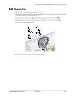
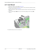
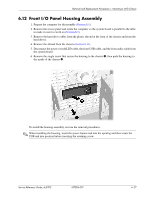
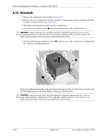
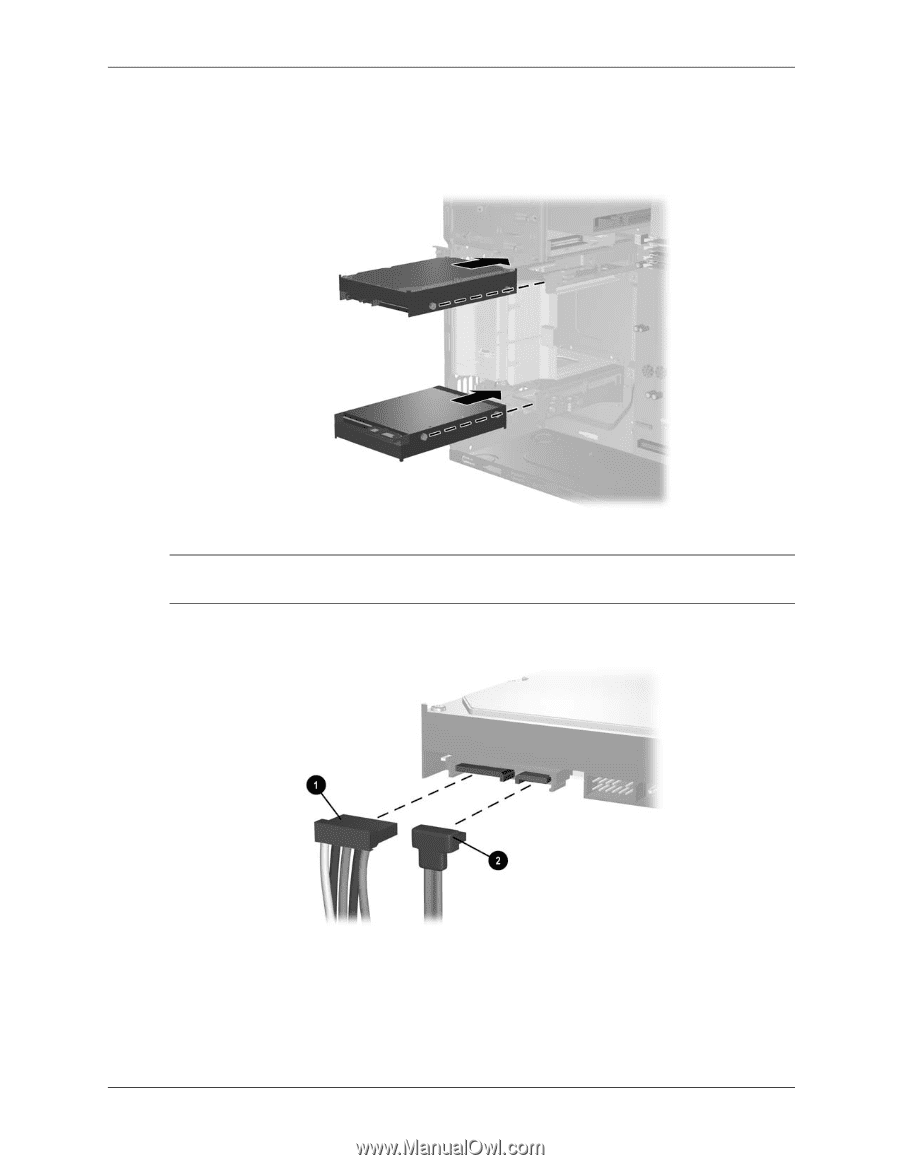
Removal and Replacement Procedures- Microtower (MT) Chassis 10. Slide the drive into the drive bay, making sure to align the guide scews with the guide slots, ubtil the drive snaps into place. The upper bay is for the primatry hard drive. The bottom bay is for the optional secondary hard drive. 11. Connect the power 1 and data 2 cables to the back of the hard drive. ✎ If you are installing a primary hard drive, use the power connector labeled P5. If you are installing a secondary hard drive use the power cable labeled P4. 12. If installing a new drive, connect the oppposite end of the data cable to the appropriate system board connector. Service Reference Guide, dc5700 437804-001 6-23
-
 1
1 -
2
-
3
-
4
-
5
-
6
-
7
-
8
-
9
-
10
-
11
-
12
-
13
-
14
-
15
-
16
-
17
-
18
-
19
-
20
-
21
-
22
-
23
-
24
-
25
-
26
-
27
-
28
-
29
-
30
-
31
-
32
-
33
-
34
-
35
-
36
-
37
-
38
-
39
-
40
-
41
-
42
-
43
-
44
-
45
-
46
-
47
-
48
-
49
-
50
-
51
-
52
-
53
-
54
-
55
-
56
-
57
-
58
-
59
-
60
-
61
-
62
-
63
-
64
-
65
-
66
-
67
-
68
-
69
-
70
-
71
-
72
-
73
-
74
-
75
-
76
-
77
-
78
-
79
-
80
-
81
-
82
-
83
-
 84
84 -
 85
85 -
 86
86 -
 87
87 -
 88
88 -
 89
89 -
 90
90 -
 91
91 -
 92
92 -
 93
93 -
 94
94 -
95
-
96
-
97
-
98
-
99
-
100
-
101
-
102
-
103
-
104
-
105
-
106
-
107
-
108
-
109
-
110
-
111
-
112
-
113
-
114
-
115
-
116
-
117
-
118
-
119
-
120
-
121
-
122
-
123
-
124
-
125
-
126
-
127
-
128
-
129
-
130
-
131
-
132
-
133
-
134
-
135
-
136
-
137
-
138
-
139
-
140
-
141
-
142
-
143
-
144
-
145
-
146
-
147
-
148
-
149
-
150
-
151
-
152
-
153
-
154
-
155
-
156
-
157
-
158
-
159
-
160
-
161
-
162
-
163
-
164
-
165
-
166
-
167
-
168
-
169
-
170
-
171
-
172
-
173
-
174
-
175
-
176
-
177
-
178
-
179
-
180
-
181
-
182
-
183
-
184
-
185
-
186
-
187
-
188
-
189
-
190
-
191
-
192
-
193
-
194
-
195
-
196
-
197
-
198
-
199
-
200
-
201
-
202
-
203
-
204
-
205
-
206
-
207
-
208
-
209
-
210
-
211
-
212
-
213
-
214
-
215
-
216
 |
 |
Service Reference Guide, dc5700
437804-001
6–23
Removal and Replacement Procedures— Microtower (MT) Chassis
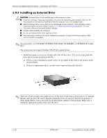
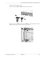
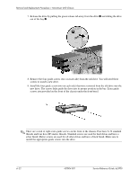
10. Slide the drive into the drive bay, making sure to align the guide scews with the guide slots,
ubtil the drive snaps into place. The upper bay is for the primatry hard drive. The bottom bay
is for the optional secondary hard drive.
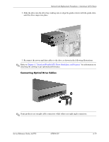
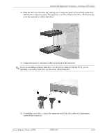
11. Connect the power 1 and data 2 cables to the back of the hard drive.
✎
If you are installing a primary hard drive, use the power connector labeled P5. If you are
installing a secondary hard drive use the power cable labeled P4.
12. If installing a new drive, connect the oppposite end of the data cable to the appropriate
system board connector.