HP Dc5700 HP Compaq dc5700 Business PC Service Reference Guide, 1st Edition - Page 85
Connecting Optical Drive Cables, Serial and Parallel ATA Drive Guidelines and Features
 |
UPC - 882780819535
View all HP Dc5700 manuals
Add to My Manuals
Save this manual to your list of manuals |
Page 85 highlights
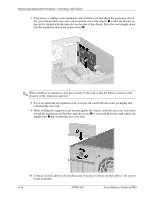
Removal and Replacement Procedures- Microtower (MT) Chassis 2. Slide the drive into the drive bay, making sure to align the guide sctrews with the guide slots, until the drive snaps into place. 3. Reconnect the power and data cables to the drive as shown in the following illustrations. ✎ Refer to Chapter 4, "Serial and Parallel ATA Drive Guidelines and Features" for information on attaching the cabling to get optimum performance. Connecting Optical Drive Cables ✎ Some products use straight cable connectors while others use right angle connectors. Service Reference Guide, dc5700 437804-001 6-19
-
 1
1 -
2
-
3
-
4
-
5
-
6
-
7
-
8
-
9
-
10
-
11
-
12
-
13
-
14
-
15
-
16
-
17
-
18
-
19
-
20
-
21
-
22
-
23
-
24
-
25
-
26
-
27
-
28
-
29
-
30
-
31
-
32
-
33
-
34
-
35
-
36
-
37
-
38
-
39
-
40
-
41
-
42
-
43
-
44
-
45
-
46
-
47
-
48
-
49
-
50
-
51
-
52
-
53
-
54
-
55
-
56
-
57
-
58
-
59
-
60
-
61
-
62
-
63
-
64
-
65
-
66
-
67
-
68
-
69
-
70
-
71
-
72
-
73
-
74
-
75
-
76
-
77
-
78
-
79
-
 80
80 -
 81
81 -
 82
82 -
 83
83 -
 84
84 -
 85
85 -
 86
86 -
 87
87 -
 88
88 -
 89
89 -
 90
90 -
91
-
92
-
93
-
94
-
95
-
96
-
97
-
98
-
99
-
100
-
101
-
102
-
103
-
104
-
105
-
106
-
107
-
108
-
109
-
110
-
111
-
112
-
113
-
114
-
115
-
116
-
117
-
118
-
119
-
120
-
121
-
122
-
123
-
124
-
125
-
126
-
127
-
128
-
129
-
130
-
131
-
132
-
133
-
134
-
135
-
136
-
137
-
138
-
139
-
140
-
141
-
142
-
143
-
144
-
145
-
146
-
147
-
148
-
149
-
150
-
151
-
152
-
153
-
154
-
155
-
156
-
157
-
158
-
159
-
160
-
161
-
162
-
163
-
164
-
165
-
166
-
167
-
168
-
169
-
170
-
171
-
172
-
173
-
174
-
175
-
176
-
177
-
178
-
179
-
180
-
181
-
182
-
183
-
184
-
185
-
186
-
187
-
188
-
189
-
190
-
191
-
192
-
193
-
194
-
195
-
196
-
197
-
198
-
199
-
200
-
201
-
202
-
203
-
204
-
205
-
206
-
207
-
208
-
209
-
210
-
211
-
212
-
213
-
214
-
215
-
216
 |
 |
Service Reference Guide, dc5700
437804-001
6–19
Removal and Replacement Procedures— Microtower (MT) Chassis
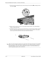
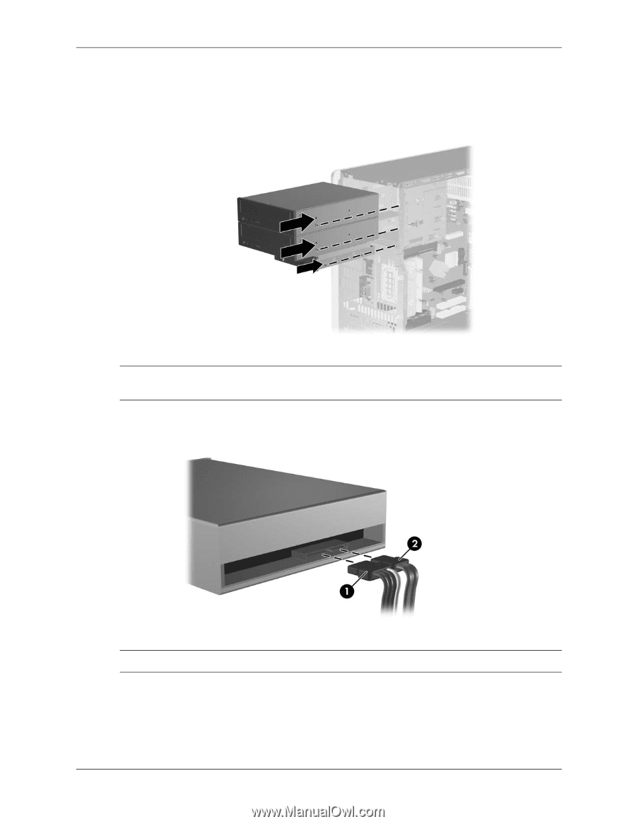
2.
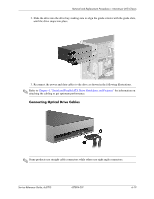
Slide the drive into the drive bay, making sure to align the guide sctrews with the guide slots,
until the drive snaps into place.
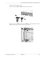
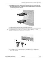
3. Reconnect the power and data cables to the drive as shown in the following illustrations.
✎
Refer to
Chapter 4, “Serial and Parallel ATA Drive Guidelines and Features”
for information on
attaching the cabling to get optimum performance.
Connecting Optical Drive Cables
✎
Some products use straight cable connectors while others use right angle connectors.