HP Dc5700 HP Compaq dc5700 Business PC Service Reference Guide, 1st Edition - Page 96
and attach the heatsink control cable to the system board.
 |
UPC - 882780819535
View all HP Dc5700 manuals
Add to My Manuals
Save this manual to your list of manuals |
Page 96 highlights
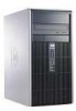
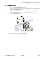
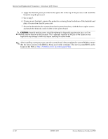
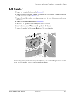
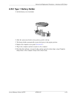
Removal and Replacement Procedures- Microtower (MT) Chassis 4. Apply the thermal grease provided in the spares kit to the top of the processor and install the heatsink atop the processor. 5. Go to step 7. 6. If using a new heatsink, remove the protective covering from the bottom of the heatsink and place it in position atop the processor. 7. Secure the heatsink to the system board and system board tray with the four captive screws and attach the heatsink control cable to the system board. Ä CAUTION: Heatsink retaining screws should be tightened in diagonally opposite pairs (as in an X) to evenly seat the heatsink on the processor. This is especially important as the pins on the socket are very fragile and any damage to them may require replacing the system board. ✎ After installing a new processor onto the system board, always update the system ROM to ensure that the latest version of the BIOS is being used on the computer. The latest system BIOS can be found on the Web at: http://h18000.www1.hp.com/support/files. 6-30 437804-001 Service Reference Guide, dc5700
-
 1
1 -
2
-
3
-
4
-
5
-
6
-
7
-
8
-
9
-
10
-
11
-
12
-
13
-
14
-
15
-
16
-
17
-
18
-
19
-
20
-
21
-
22
-
23
-
24
-
25
-
26
-
27
-
28
-
29
-
30
-
31
-
32
-
33
-
34
-
35
-
36
-
37
-
38
-
39
-
40
-
41
-
42
-
43
-
44
-
45
-
46
-
47
-
48
-
49
-
50
-
51
-
52
-
53
-
54
-
55
-
56
-
57
-
58
-
59
-
60
-
61
-
62
-
63
-
64
-
65
-
66
-
67
-
68
-
69
-
70
-
71
-
72
-
73
-
74
-
75
-
76
-
77
-
78
-
79
-
80
-
81
-
82
-
83
-
84
-
85
-
86
-
87
-
88
-
89
-
90
-
 91
91 -
 92
92 -
 93
93 -
 94
94 -
 95
95 -
 96
96 -
 97
97 -
 98
98 -
 99
99 -
 100
100 -
 101
101 -
102
-
103
-
104
-
105
-
106
-
107
-
108
-
109
-
110
-
111
-
112
-
113
-
114
-
115
-
116
-
117
-
118
-
119
-
120
-
121
-
122
-
123
-
124
-
125
-
126
-
127
-
128
-
129
-
130
-
131
-
132
-
133
-
134
-
135
-
136
-
137
-
138
-
139
-
140
-
141
-
142
-
143
-
144
-
145
-
146
-
147
-
148
-
149
-
150
-
151
-
152
-
153
-
154
-
155
-
156
-
157
-
158
-
159
-
160
-
161
-
162
-
163
-
164
-
165
-
166
-
167
-
168
-
169
-
170
-
171
-
172
-
173
-
174
-
175
-
176
-
177
-
178
-
179
-
180
-
181
-
182
-
183
-
184
-
185
-
186
-
187
-
188
-
189
-
190
-
191
-
192
-
193
-
194
-
195
-
196
-
197
-
198
-
199
-
200
-
201
-
202
-
203
-
204
-
205
-
206
-
207
-
208
-
209
-
210
-
211
-
212
-
213
-
214
-
215
-
216
 |
 |