HP Dc5700 HP Compaq dc5700 Business PC Service Reference Guide, 1st Edition - Page 135
System Board
 |
UPC - 882780819535
View all HP Dc5700 manuals
Add to My Manuals
Save this manual to your list of manuals |
Page 135 highlights
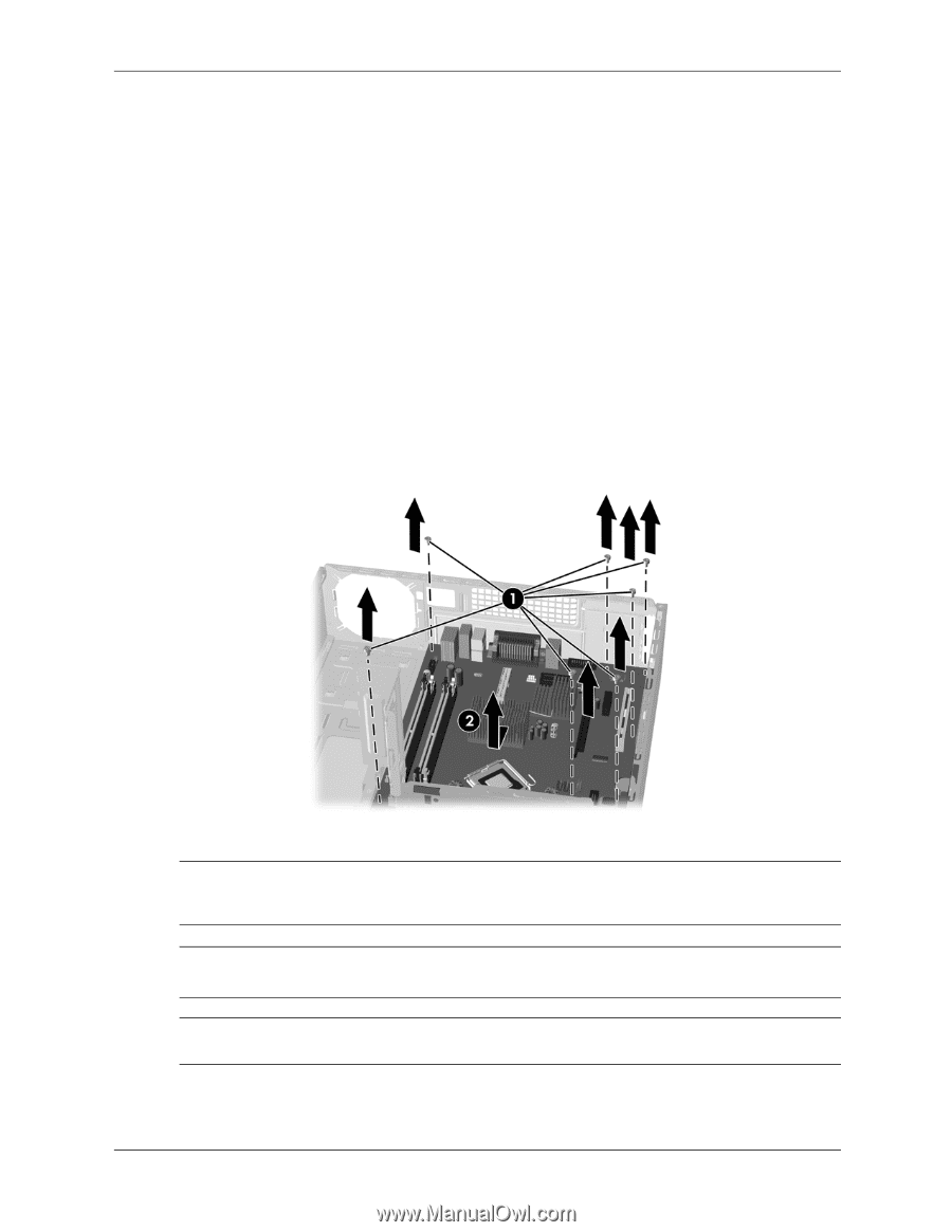
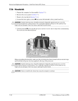
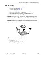
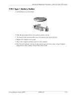
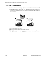
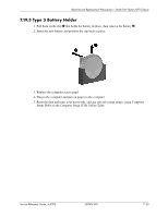
Removal and Replacement Procedures- Small Form Factor (SFF) Chassis 7.18 System Board 1. Prepare the computer for disassembly (Section 7.1). 2. Remove the access panel (Section 7.3). 3. Remove all PCI and PCI Express expansion boards (Section 7.9). 4. Remove the fan shroud from the chassis (Section 7.11). 5. Remove the optical drive (Section 7.7.2). 6. Rotate the optical drive retainer to its upright position. 7. Remove all memory modules (Section 7.8). 8. Disconnect all data and power cables from the system board. 9. Remove the power supply (Section 7.10). 10. Remove the system board retaining screws 1 , slide the board towards the front of the chassis, then lift the board from the chassis 2. To install the system board, reverse the removal procedure. Ä CAUTION: Before reinstalling the heatsink you must clean the top of the processor and the bottom of the heatsink with an alcohol pad supplied in the spares kit. After the alcohol has evaporated, apply thermal grease to the top of the processor from the syringe supplied in the spares kit. ✎ When reinstalling the system board it is important to secure the system board and tray to the chassis with the long retaining screw before performing any subsequent steps. Ä CAUTION: When reconnecting the cables it is important that they be positioned so they do not interfere with the rotation of the drive cage or power supply. Service Reference Guide, dc5700 437804-001 7-31
-
 1
1 -
2
-
3
-
4
-
5
-
6
-
7
-
8
-
9
-
10
-
11
-
12
-
13
-
14
-
15
-
16
-
17
-
18
-
19
-
20
-
21
-
22
-
23
-
24
-
25
-
26
-
27
-
28
-
29
-
30
-
31
-
32
-
33
-
34
-
35
-
36
-
37
-
38
-
39
-
40
-
41
-
42
-
43
-
44
-
45
-
46
-
47
-
48
-
49
-
50
-
51
-
52
-
53
-
54
-
55
-
56
-
57
-
58
-
59
-
60
-
61
-
62
-
63
-
64
-
65
-
66
-
67
-
68
-
69
-
70
-
71
-
72
-
73
-
74
-
75
-
76
-
77
-
78
-
79
-
80
-
81
-
82
-
83
-
84
-
85
-
86
-
87
-
88
-
89
-
90
-
91
-
92
-
93
-
94
-
95
-
96
-
97
-
98
-
99
-
100
-
101
-
102
-
103
-
104
-
105
-
106
-
107
-
108
-
109
-
110
-
111
-
112
-
113
-
114
-
115
-
116
-
117
-
118
-
119
-
120
-
121
-
122
-
123
-
124
-
125
-
126
-
127
-
128
-
129
-
 130
130 -
 131
131 -
 132
132 -
 133
133 -
 134
134 -
 135
135 -
 136
136 -
 137
137 -
 138
138 -
 139
139 -
 140
140 -
141
-
142
-
143
-
144
-
145
-
146
-
147
-
148
-
149
-
150
-
151
-
152
-
153
-
154
-
155
-
156
-
157
-
158
-
159
-
160
-
161
-
162
-
163
-
164
-
165
-
166
-
167
-
168
-
169
-
170
-
171
-
172
-
173
-
174
-
175
-
176
-
177
-
178
-
179
-
180
-
181
-
182
-
183
-
184
-
185
-
186
-
187
-
188
-
189
-
190
-
191
-
192
-
193
-
194
-
195
-
196
-
197
-
198
-
199
-
200
-
201
-
202
-
203
-
204
-
205
-
206
-
207
-
208
-
209
-
210
-
211
-
212
-
213
-
214
-
215
-
216
 |
 |