HP Visualize J5000 hp Visualize J5000, J7000 workstations owner's guide (a4476 - Page 144
DDS Tape Drive
 |
View all HP Visualize J5000 manuals
Add to My Manuals
Save this manual to your list of manuals |
Page 144 highlights
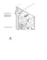
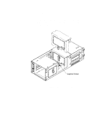
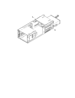
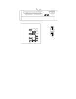
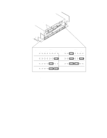
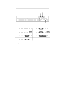
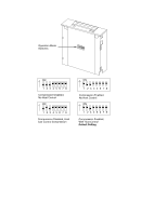
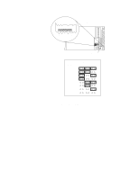
DDS Tape Drive The DDS tape drive ships with the drive set to SCSI ID address 3 and the Operation Mode switches set for correct drive operation. We recommend keeping the address setting at 3 unless it is used by another device. CAUTION: SCSI tape drives are susceptible to mechanical and electrostatic shock. When handling the drive, always wear the static-grounding wrist strap that came in the DDS tape drive kit. Always handle the drive carefully. If you need to change the DDS tape drive's address or operation mode, follow these instructions, referring to Figure A-7 for the DDS-DC drive, Figure A-8 for the DDS-2 drive, and Figure A-9 for operation mode. If you do not need to change the drive's address or operation mode, go to Step 10 of this installation procedure. 1. Locate the jumpers at the back of the DDS tape drive. 2. To change the jumper settings, use needlenose pliers to set the drive's SCSI ID to an address that is not used by another SCSI device. Check that the other jumpers are set correctly. NOTICE: Do not use SCSI ID 7 for your DDS tape drive's SCSI address. The host SCSI controller uses SCSI ID 7. 3. Use needlenose pliers to remove the SCSI terminators, if still attached to the drive. 4. If you need to change the Operation Mode switches, locate the switches on the underside of the DDS tape drive. Switches 1 and 2 are used to configure the data compression operation mode. Switches 3 through 8 are used to specify drive connectivity and functionality according to host or customer requirements. The default setting is all switches ON. Figure A-9 shows the available options. B-16
-
 1
1 -
2
-
3
-
4
-
5
-
6
-
7
-
8
-
9
-
10
-
11
-
12
-
13
-
14
-
15
-
16
-
17
-
18
-
19
-
20
-
21
-
22
-
23
-
24
-
25
-
26
-
27
-
28
-
29
-
30
-
31
-
32
-
33
-
34
-
35
-
36
-
37
-
38
-
39
-
40
-
41
-
42
-
43
-
44
-
45
-
46
-
47
-
48
-
49
-
50
-
51
-
52
-
53
-
54
-
55
-
56
-
57
-
58
-
59
-
60
-
61
-
62
-
63
-
64
-
65
-
66
-
67
-
68
-
69
-
70
-
71
-
72
-
73
-
74
-
75
-
76
-
77
-
78
-
79
-
80
-
81
-
82
-
83
-
84
-
85
-
86
-
87
-
88
-
89
-
90
-
91
-
92
-
93
-
94
-
95
-
96
-
97
-
98
-
99
-
100
-
101
-
102
-
103
-
104
-
105
-
106
-
107
-
108
-
109
-
110
-
111
-
112
-
113
-
114
-
115
-
116
-
117
-
118
-
119
-
120
-
121
-
122
-
123
-
124
-
125
-
126
-
127
-
128
-
129
-
130
-
131
-
132
-
133
-
134
-
135
-
136
-
137
-
138
-
 139
139 -
 140
140 -
 141
141 -
 142
142 -
 143
143 -
 144
144 -
 145
145 -
 146
146 -
 147
147 -
 148
148 -
 149
149 -
150
-
151
-
152
-
153
-
154
-
155
-
156
-
157
-
158
-
159
-
160
-
161
-
162
-
163
-
164
-
165
-
166
-
167
-
168
-
169
-
170
-
171
-
172
-
173
-
174
-
175
-
176
-
177
-
178
-
179
-
180
-
181
-
182
-
183
-
184
-
185
-
186
-
187
-
188
-
189
-
190
-
191
-
192
-
193
-
194
-
195
-
196
-
197
-
198
-
199
-
200
-
201
-
202
-
203
-
204
-
205
-
206
-
207
-
208
-
209
-
210
-
211
-
212
-
213
-
214
-
215
-
216
-
217
-
218
-
219
-
220
-
221
-
222
-
223
-
224
-
225
-
226
-
227
-
228
-
229
-
230
-
231
-
232
-
233
-
234
-
235
-
236
-
237
-
238
-
239
-
240
-
241
-
242
-
243
-
244
-
245
-
246
-
247
-
248
-
249
-
250
-
251
-
252
-
253
-
254
-
255
-
256
-
257
-
258
-
259
-
260
-
261
-
262
-
263
-
264
-
265
-
266
-
267
-
268
-
269
-
270
-
271
-
272
-
273
 |
 |