HP Visualize J5000 hp Visualize J5000, J7000 workstations owner's guide (a4476 - Page 173
A-26., CPU Shroud Location
 |
View all HP Visualize J5000 manuals
Add to My Manuals
Save this manual to your list of manuals |
Page 173 highlights
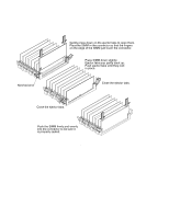
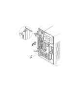
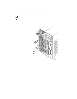
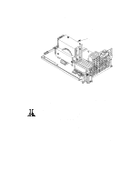
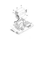
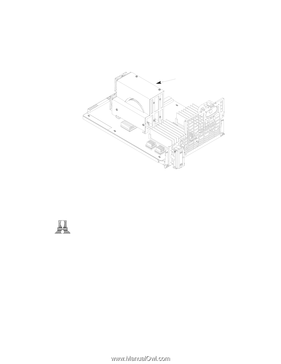
4. Pull the CPU Assembly straight out and place on a flat surface with an antistatic mat. 5. Locate the CPU shroud as shown in Figure A-26. CPU shroud Figure A-26. CPU Shroud Location 6. Disconnect the fan cable from the system board. Refer to Figure A-27. CAUTION: Be sure to reconnect the fan cable when you have finished installing the processor. Failure to reconnect the fan could cause the unit to overhead and damage the processor(s). 7. Remove the six screws attaching the CPU shroud to the system board and pull the shroud straight up. Set the shroud aside. B-45
-
 1
1 -
2
-
3
-
4
-
5
-
6
-
7
-
8
-
9
-
10
-
11
-
12
-
13
-
14
-
15
-
16
-
17
-
18
-
19
-
20
-
21
-
22
-
23
-
24
-
25
-
26
-
27
-
28
-
29
-
30
-
31
-
32
-
33
-
34
-
35
-
36
-
37
-
38
-
39
-
40
-
41
-
42
-
43
-
44
-
45
-
46
-
47
-
48
-
49
-
50
-
51
-
52
-
53
-
54
-
55
-
56
-
57
-
58
-
59
-
60
-
61
-
62
-
63
-
64
-
65
-
66
-
67
-
68
-
69
-
70
-
71
-
72
-
73
-
74
-
75
-
76
-
77
-
78
-
79
-
80
-
81
-
82
-
83
-
84
-
85
-
86
-
87
-
88
-
89
-
90
-
91
-
92
-
93
-
94
-
95
-
96
-
97
-
98
-
99
-
100
-
101
-
102
-
103
-
104
-
105
-
106
-
107
-
108
-
109
-
110
-
111
-
112
-
113
-
114
-
115
-
116
-
117
-
118
-
119
-
120
-
121
-
122
-
123
-
124
-
125
-
126
-
127
-
128
-
129
-
130
-
131
-
132
-
133
-
134
-
135
-
136
-
137
-
138
-
139
-
140
-
141
-
142
-
143
-
144
-
145
-
146
-
147
-
148
-
149
-
150
-
151
-
152
-
153
-
154
-
155
-
156
-
157
-
158
-
159
-
160
-
161
-
162
-
163
-
164
-
165
-
166
-
167
-
 168
168 -
 169
169 -
 170
170 -
 171
171 -
 172
172 -
 173
173 -
 174
174 -
 175
175 -
 176
176 -
 177
177 -
 178
178 -
179
-
180
-
181
-
182
-
183
-
184
-
185
-
186
-
187
-
188
-
189
-
190
-
191
-
192
-
193
-
194
-
195
-
196
-
197
-
198
-
199
-
200
-
201
-
202
-
203
-
204
-
205
-
206
-
207
-
208
-
209
-
210
-
211
-
212
-
213
-
214
-
215
-
216
-
217
-
218
-
219
-
220
-
221
-
222
-
223
-
224
-
225
-
226
-
227
-
228
-
229
-
230
-
231
-
232
-
233
-
234
-
235
-
236
-
237
-
238
-
239
-
240
-
241
-
242
-
243
-
244
-
245
-
246
-
247
-
248
-
249
-
250
-
251
-
252
-
253
-
254
-
255
-
256
-
257
-
258
-
259
-
260
-
261
-
262
-
263
-
264
-
265
-
266
-
267
-
268
-
269
-
270
-
271
-
272
-
273
 |
 |
B-45
4.
Pull the CPU Assembly straight out and place on a flat surface
with an antistatic mat.
5.
Locate the CPU shroud as shown in Figure A–26.
CPU shroud
Figure A–26.
CPU Shroud Location
6.
Disconnect the fan cable from the system board. Refer to Figure
A–27.
CAUTION:
Be sure to reconnect the fan cable when you
have finished installing the processor. Failure to
reconnect the fan could cause the unit to over-
head and damage the processor(s).
7.
Remove the six screws attaching the CPU shroud to the system
board and pull the shroud straight up. Set the shroud aside.