HP Visualize J5000 hp Visualize J5000, J7000 workstations owner's guide (a4476 - Page 167
Pair 2 1A, 1B, Pair 3 2A, 2B, and so on.
 |
View all HP Visualize J5000 manuals
Add to My Manuals
Save this manual to your list of manuals |
Page 167 highlights
Memory SIMMs Position Guide Figure A-21. CPU Assembly Orientation 7. Refer to the Position Guide on the CPU board that states, "
-
 1
1 -
2
-
3
-
4
-
5
-
6
-
7
-
8
-
9
-
10
-
11
-
12
-
13
-
14
-
15
-
16
-
17
-
18
-
19
-
20
-
21
-
22
-
23
-
24
-
25
-
26
-
27
-
28
-
29
-
30
-
31
-
32
-
33
-
34
-
35
-
36
-
37
-
38
-
39
-
40
-
41
-
42
-
43
-
44
-
45
-
46
-
47
-
48
-
49
-
50
-
51
-
52
-
53
-
54
-
55
-
56
-
57
-
58
-
59
-
60
-
61
-
62
-
63
-
64
-
65
-
66
-
67
-
68
-
69
-
70
-
71
-
72
-
73
-
74
-
75
-
76
-
77
-
78
-
79
-
80
-
81
-
82
-
83
-
84
-
85
-
86
-
87
-
88
-
89
-
90
-
91
-
92
-
93
-
94
-
95
-
96
-
97
-
98
-
99
-
100
-
101
-
102
-
103
-
104
-
105
-
106
-
107
-
108
-
109
-
110
-
111
-
112
-
113
-
114
-
115
-
116
-
117
-
118
-
119
-
120
-
121
-
122
-
123
-
124
-
125
-
126
-
127
-
128
-
129
-
130
-
131
-
132
-
133
-
134
-
135
-
136
-
137
-
138
-
139
-
140
-
141
-
142
-
143
-
144
-
145
-
146
-
147
-
148
-
149
-
150
-
151
-
152
-
153
-
154
-
155
-
156
-
157
-
158
-
159
-
160
-
161
-
 162
162 -
 163
163 -
 164
164 -
 165
165 -
 166
166 -
 167
167 -
 168
168 -
 169
169 -
 170
170 -
 171
171 -
 172
172 -
173
-
174
-
175
-
176
-
177
-
178
-
179
-
180
-
181
-
182
-
183
-
184
-
185
-
186
-
187
-
188
-
189
-
190
-
191
-
192
-
193
-
194
-
195
-
196
-
197
-
198
-
199
-
200
-
201
-
202
-
203
-
204
-
205
-
206
-
207
-
208
-
209
-
210
-
211
-
212
-
213
-
214
-
215
-
216
-
217
-
218
-
219
-
220
-
221
-
222
-
223
-
224
-
225
-
226
-
227
-
228
-
229
-
230
-
231
-
232
-
233
-
234
-
235
-
236
-
237
-
238
-
239
-
240
-
241
-
242
-
243
-
244
-
245
-
246
-
247
-
248
-
249
-
250
-
251
-
252
-
253
-
254
-
255
-
256
-
257
-
258
-
259
-
260
-
261
-
262
-
263
-
264
-
265
-
266
-
267
-
268
-
269
-
270
-
271
-
272
-
273
 |
 |
B-39
Memory
SIMMs
Position Guide
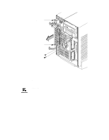
Figure A–21.
CPU Assembly Orientation
7.
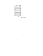
Refer to the Position Guide on the CPU board that states,
“<–– POSITION MEM MODULE AS SHOWN,” as shown in
Figure A–21.
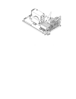
8.
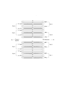
Install pairs of SIMMs in the following order: Pair 1 (0A, 0B),
Pair 2 (1A, 1B), Pair 3 (2A, 2B), and so on.
This workstation has 16 memory slots, labeled 0A, 0B through
7A, 7B. Memory can be configured from 32 MB to 256 MB
installed in pairs of 16 MB SIMMs. Memory can be configured
from 128 MB to 768 MB (128 MB to 1 GB if you are running
HP-UX 10.0), installed in pairs of 64 MB SIMMs, or memory
can be configured from 32 MB to 768 MB (1 GB if you are run-
ning HP-UX 10.0) in combinations of pairs of 32 MB and 128
MB SIMM pairs. Memory SIMMs must be installed in pairs of
equal size, with 128 MB SIMM pairs installed first, followed by
32 MB SIMM pairs. Figure A–22 gives the recommended order
for installing pairs of SIMMs.