HP Visualize J5000 hp Visualize J5000, J7000 workstations owner's guide (a4476 - Page 175
AA BB
 |
View all HP Visualize J5000 manuals
Add to My Manuals
Save this manual to your list of manuals |
Page 175 highlights
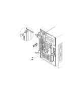
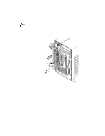
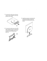
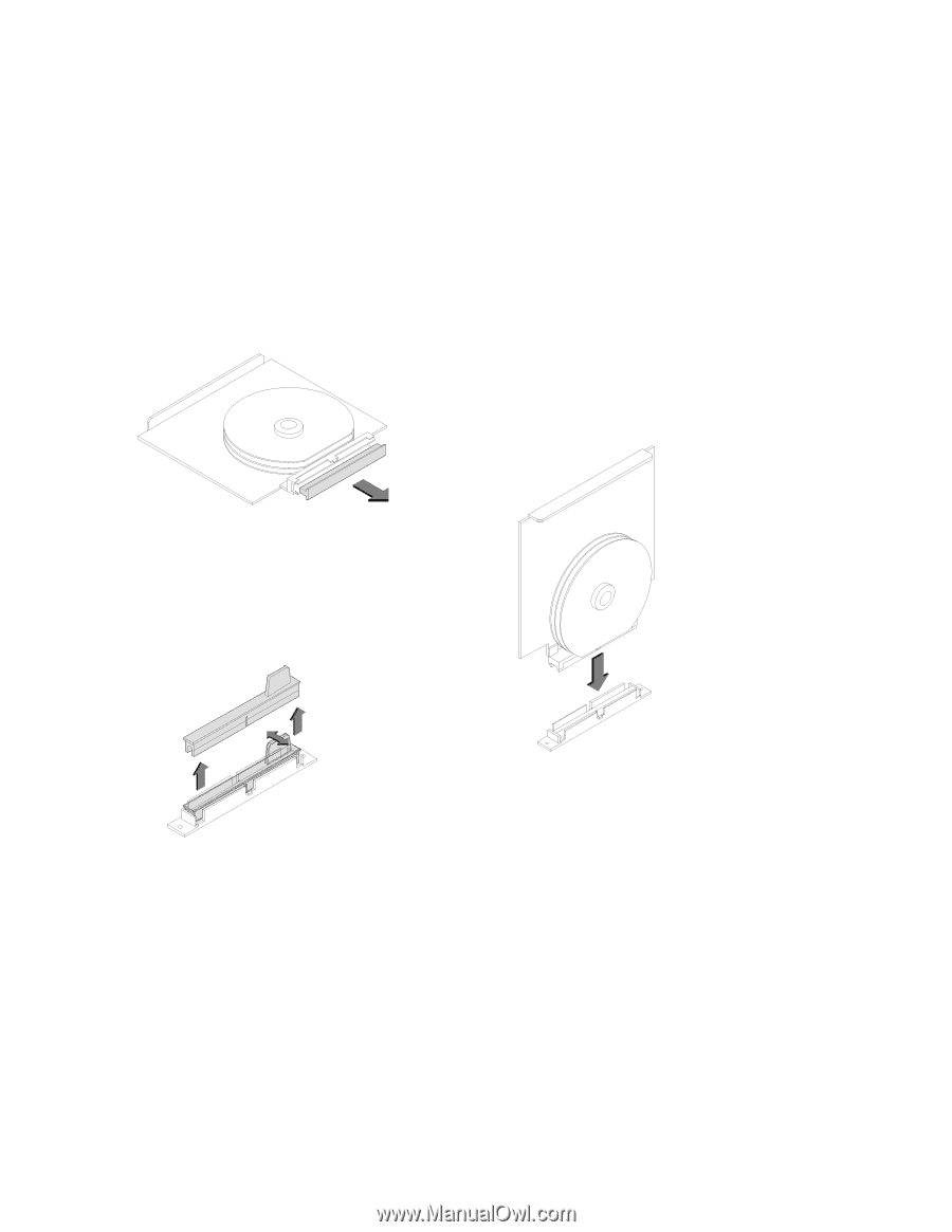
• Processors are shipped with a dust cover (A) over the connector. • There are two connectors on the CPU board for processors. If one of these connectors is not being used, it will have a dust cover (B) over the connector. To remove these dust covers, follow the steps in Figure A-28. 1. To remove the dust cover on the proĆ cessor module, grasp the cover and pull the cover evenly. 3. Install the processor module into the connector by lining it up over the connector and pressing firmly and evenly. A 2. To remove the dust cover on the CPU board, grasp the tab on the right side of the cover and gently rock the covĆ er back and forth while pulling it gently up. B Figure A-28. Removing CPU and Connector Dust Covers B-47
-
 1
1 -
2
-
3
-
4
-
5
-
6
-
7
-
8
-
9
-
10
-
11
-
12
-
13
-
14
-
15
-
16
-
17
-
18
-
19
-
20
-
21
-
22
-
23
-
24
-
25
-
26
-
27
-
28
-
29
-
30
-
31
-
32
-
33
-
34
-
35
-
36
-
37
-
38
-
39
-
40
-
41
-
42
-
43
-
44
-
45
-
46
-
47
-
48
-
49
-
50
-
51
-
52
-
53
-
54
-
55
-
56
-
57
-
58
-
59
-
60
-
61
-
62
-
63
-
64
-
65
-
66
-
67
-
68
-
69
-
70
-
71
-
72
-
73
-
74
-
75
-
76
-
77
-
78
-
79
-
80
-
81
-
82
-
83
-
84
-
85
-
86
-
87
-
88
-
89
-
90
-
91
-
92
-
93
-
94
-
95
-
96
-
97
-
98
-
99
-
100
-
101
-
102
-
103
-
104
-
105
-
106
-
107
-
108
-
109
-
110
-
111
-
112
-
113
-
114
-
115
-
116
-
117
-
118
-
119
-
120
-
121
-
122
-
123
-
124
-
125
-
126
-
127
-
128
-
129
-
130
-
131
-
132
-
133
-
134
-
135
-
136
-
137
-
138
-
139
-
140
-
141
-
142
-
143
-
144
-
145
-
146
-
147
-
148
-
149
-
150
-
151
-
152
-
153
-
154
-
155
-
156
-
157
-
158
-
159
-
160
-
161
-
162
-
163
-
164
-
165
-
166
-
167
-
168
-
169
-
 170
170 -
 171
171 -
 172
172 -
 173
173 -
 174
174 -
 175
175 -
 176
176 -
 177
177 -
 178
178 -
 179
179 -
 180
180 -
181
-
182
-
183
-
184
-
185
-
186
-
187
-
188
-
189
-
190
-
191
-
192
-
193
-
194
-
195
-
196
-
197
-
198
-
199
-
200
-
201
-
202
-
203
-
204
-
205
-
206
-
207
-
208
-
209
-
210
-
211
-
212
-
213
-
214
-
215
-
216
-
217
-
218
-
219
-
220
-
221
-
222
-
223
-
224
-
225
-
226
-
227
-
228
-
229
-
230
-
231
-
232
-
233
-
234
-
235
-
236
-
237
-
238
-
239
-
240
-
241
-
242
-
243
-
244
-
245
-
246
-
247
-
248
-
249
-
250
-
251
-
252
-
253
-
254
-
255
-
256
-
257
-
258
-
259
-
260
-
261
-
262
-
263
-
264
-
265
-
266
-
267
-
268
-
269
-
270
-
271
-
272
-
273
 |
 |
B-47
•
Processors are shipped with a dust cover (
A
) over the connector.
•
There are two connectors on the CPU board for processors. If one
of these connectors is not being used, it will have a dust cover (
B
)
over the connector.
To remove these dust covers, follow the steps in Figure A–28.
A
B
To
remove the dust
cover on the proĆ
cessor
module, grasp the cover and
pull the cover evenly.
To
remove the dust
cover on the CPU
board,
grasp the tab on the right
side
of
the cover
and gently rock
the covĆ
er
back
and forth while pulling
it
gently
up.
Install the processor module into
the
connector by lining it
up over the
connector and pressing firmly and
evenly.
1.
3.
2.
Figure A–28.
Removing CPU and Connector Dust Covers