HP Visualize J5000 hp Visualize J5000, J7000 workstations owner's guide (a4476 - Page 153
A-14.
 |
View all HP Visualize J5000 manuals
Add to My Manuals
Save this manual to your list of manuals |
Page 153 highlights
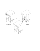
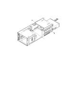
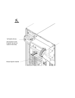
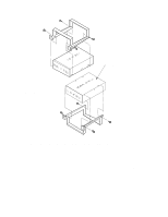
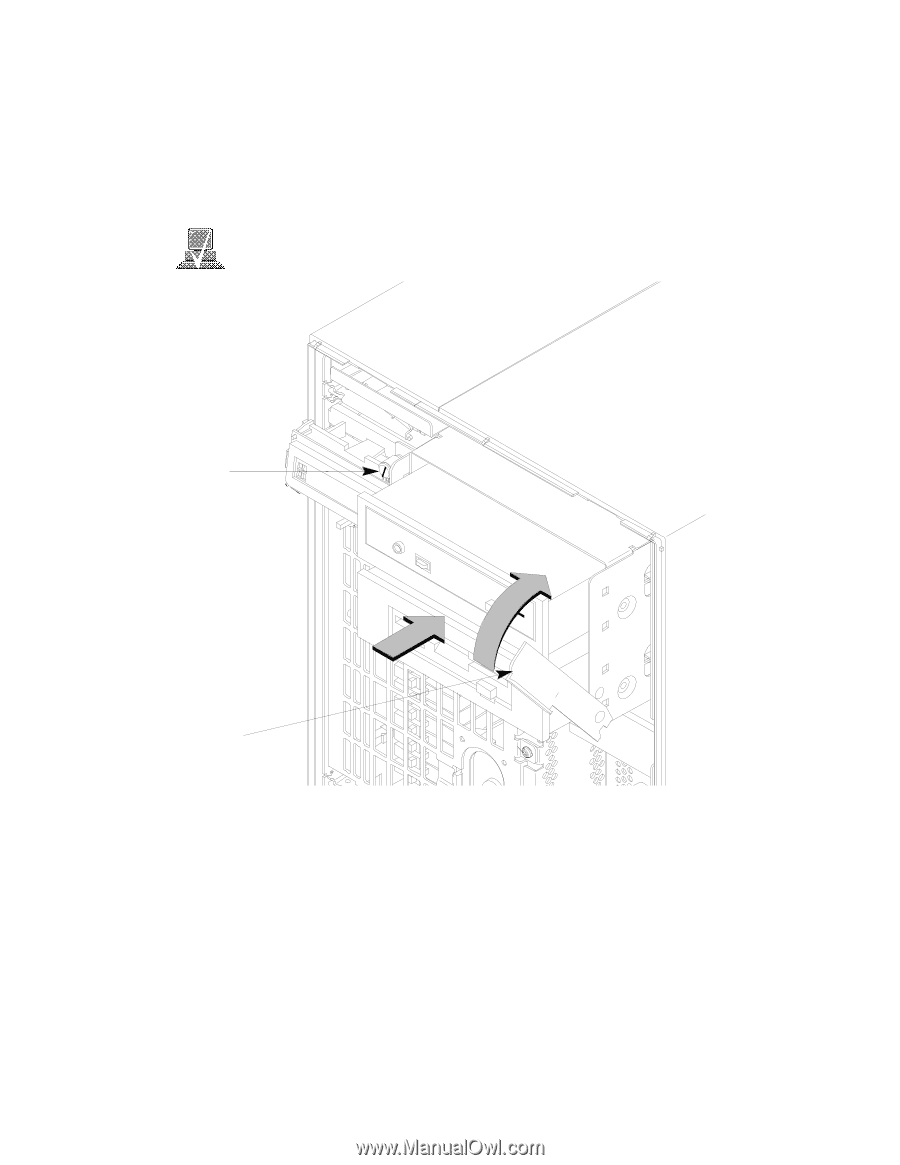
15. Push the drawer ejector handle up until the Storage Assembly slides all the way into the system unit and secure the two captive screws on the left of the Storage Assembly, as shown in Figure A-14. NOTICE: If the ejector handle is not pushed completely in, you may not have proper seating of the SCSI PCB interconnect to the backplane. 1st Captive Screw (2nd Captive screw is below 1st, but not visible in this view) Drawer Ejector Handle Figure A-14. Replacing the Storage Drawer Assembly B-25
-
 1
1 -
2
-
3
-
4
-
5
-
6
-
7
-
8
-
9
-
10
-
11
-
12
-
13
-
14
-
15
-
16
-
17
-
18
-
19
-
20
-
21
-
22
-
23
-
24
-
25
-
26
-
27
-
28
-
29
-
30
-
31
-
32
-
33
-
34
-
35
-
36
-
37
-
38
-
39
-
40
-
41
-
42
-
43
-
44
-
45
-
46
-
47
-
48
-
49
-
50
-
51
-
52
-
53
-
54
-
55
-
56
-
57
-
58
-
59
-
60
-
61
-
62
-
63
-
64
-
65
-
66
-
67
-
68
-
69
-
70
-
71
-
72
-
73
-
74
-
75
-
76
-
77
-
78
-
79
-
80
-
81
-
82
-
83
-
84
-
85
-
86
-
87
-
88
-
89
-
90
-
91
-
92
-
93
-
94
-
95
-
96
-
97
-
98
-
99
-
100
-
101
-
102
-
103
-
104
-
105
-
106
-
107
-
108
-
109
-
110
-
111
-
112
-
113
-
114
-
115
-
116
-
117
-
118
-
119
-
120
-
121
-
122
-
123
-
124
-
125
-
126
-
127
-
128
-
129
-
130
-
131
-
132
-
133
-
134
-
135
-
136
-
137
-
138
-
139
-
140
-
141
-
142
-
143
-
144
-
145
-
146
-
147
-
 148
148 -
 149
149 -
 150
150 -
 151
151 -
 152
152 -
 153
153 -
 154
154 -
 155
155 -
 156
156 -
 157
157 -
 158
158 -
159
-
160
-
161
-
162
-
163
-
164
-
165
-
166
-
167
-
168
-
169
-
170
-
171
-
172
-
173
-
174
-
175
-
176
-
177
-
178
-
179
-
180
-
181
-
182
-
183
-
184
-
185
-
186
-
187
-
188
-
189
-
190
-
191
-
192
-
193
-
194
-
195
-
196
-
197
-
198
-
199
-
200
-
201
-
202
-
203
-
204
-
205
-
206
-
207
-
208
-
209
-
210
-
211
-
212
-
213
-
214
-
215
-
216
-
217
-
218
-
219
-
220
-
221
-
222
-
223
-
224
-
225
-
226
-
227
-
228
-
229
-
230
-
231
-
232
-
233
-
234
-
235
-
236
-
237
-
238
-
239
-
240
-
241
-
242
-
243
-
244
-
245
-
246
-
247
-
248
-
249
-
250
-
251
-
252
-
253
-
254
-
255
-
256
-
257
-
258
-
259
-
260
-
261
-
262
-
263
-
264
-
265
-
266
-
267
-
268
-
269
-
270
-
271
-
272
-
273
 |
 |
B-25
15.
Push the drawer ejector handle up until the Storage Assembly
slides all the way into the system unit and secure the two captive
screws on the left of the Storage Assembly, as shown in
Figure A–14.
NOTICE:
If the ejector handle is not pushed completely
in, you may not have proper seating of the SCSI
PCB interconnect to the backplane.
1st Captive Screw
(2nd Captive screw
is
below
1st,
but
not
visible in this
view)
Drawer
Ejector
Handle
Figure A–14.
Replacing the Storage Drawer Assembly