Dell PowerConnect W-IAP92 Dell Instant 6.1.3.4-3.1.0.0 User Guide - Page 228
Routing Profile Configuration, Primary host, Backup host, Enabled, Preemption, Routing Table
 |
View all Dell PowerConnect W-IAP92 manuals
Add to My Manuals
Save this manual to your list of manuals |
Page 228 highlights
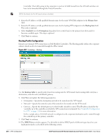
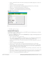
Controller. The traffic going to the corporate is send via L2 GRE tunnel from the AP itself and does not have to be forwarded through the Virtual Controller. NOTE: By default, the Per-AP tunnel option is disabled. 4. Enter the IP address or fully qualified domain name for the main VPN/GRE endpoint in the Primary host field. 5. Enter the IP address or fully qualified domain name for the backup VPN endpoint in the Backup host field. This entry is optional. 6. Select Enabled from the Preemption drop-down list to switch back to the primary host when and if it becomes available again. This step is optional. 7. Click Next to continue. Routing Profile Configuration Instant can terminate VPN connections on Dell Mobility Controllers. The Routing profile defines the corporate subnets which need to be tunneled through the IPSec tunnel. Figure 207 Tunneling- Routing Use the Routing Table to specify policy based on routing into the VPN tunnel. Each routing table entry has a destination, network mask, and default gateway. 8. Click New and update the following parameters. Destination- Specify the destination network to be routed into the VPN tunnel. Netmask- Specify the network mask of the network to be routed into the VPN tunnel. Gateway- Specify the default gateway to which traffic should be routed. This IP address should be the 'controller-ip' of the controller on which the VPN connection is terminated. See "Controller Configuration for VPN" on page 241 for more information. In the example above, 10.0.0.0/8 network is configured as the corporate destination and is routed through the controller-ip of the primary controller. 9. Click Next to continue. 10. The DHCP Server window appears. Use this table to define DHCP pools of different types based on your deployment modes as described in the following section. 228 | VPN Configuration Dell PowerConnect W-Series Instant Access Point 6.1.3.4-3.1.0.0 | User Guide
-
 1
1 -
2
-
3
-
4
-
5
-
6
-
7
-
8
-
9
-
10
-
11
-
12
-
13
-
14
-
15
-
16
-
17
-
18
-
19
-
20
-
21
-
22
-
23
-
24
-
25
-
26
-
27
-
28
-
29
-
30
-
31
-
32
-
33
-
34
-
35
-
36
-
37
-
38
-
39
-
40
-
41
-
42
-
43
-
44
-
45
-
46
-
47
-
48
-
49
-
50
-
51
-
52
-
53
-
54
-
55
-
56
-
57
-
58
-
59
-
60
-
61
-
62
-
63
-
64
-
65
-
66
-
67
-
68
-
69
-
70
-
71
-
72
-
73
-
74
-
75
-
76
-
77
-
78
-
79
-
80
-
81
-
82
-
83
-
84
-
85
-
86
-
87
-
88
-
89
-
90
-
91
-
92
-
93
-
94
-
95
-
96
-
97
-
98
-
99
-
100
-
101
-
102
-
103
-
104
-
105
-
106
-
107
-
108
-
109
-
110
-
111
-
112
-
113
-
114
-
115
-
116
-
117
-
118
-
119
-
120
-
121
-
122
-
123
-
124
-
125
-
126
-
127
-
128
-
129
-
130
-
131
-
132
-
133
-
134
-
135
-
136
-
137
-
138
-
139
-
140
-
141
-
142
-
143
-
144
-
145
-
146
-
147
-
148
-
149
-
150
-
151
-
152
-
153
-
154
-
155
-
156
-
157
-
158
-
159
-
160
-
161
-
162
-
163
-
164
-
165
-
166
-
167
-
168
-
169
-
170
-
171
-
172
-
173
-
174
-
175
-
176
-
177
-
178
-
179
-
180
-
181
-
182
-
183
-
184
-
185
-
186
-
187
-
188
-
189
-
190
-
191
-
192
-
193
-
194
-
195
-
196
-
197
-
198
-
199
-
200
-
201
-
202
-
203
-
204
-
205
-
206
-
207
-
208
-
209
-
210
-
211
-
212
-
213
-
214
-
215
-
216
-
217
-
218
-
219
-
220
-
221
-
222
-
 223
223 -
 224
224 -
 225
225 -
 226
226 -
 227
227 -
 228
228 -
 229
229 -
 230
230 -
 231
231 -
 232
232 -
 233
233 -
234
-
235
-
236
-
237
-
238
-
239
-
240
-
241
-
242
-
243
-
244
-
245
-
246
 |
 |
