Dell PowerEdge T100 Hardware Owner's Manual - Page 15
Power Supply Indicators, Getting Started Guide - specification
 |
View all Dell PowerEdge T100 manuals
Add to My Manuals
Save this manual to your list of manuals |
Page 15 highlights
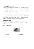
Table 1-3. NIC Indicator Codes Indicator Type Indicator Code Activity Off Blinking Link Off Yellow Orange Green Description When off at the same time that the link indicator is off, the NIC is not connected to the network or the NIC is disabled in the System Setup program. See "Using the System Setup Program" on page 29. Indicates that network data is being sent or received. When off at the same time that the activity indicator is off, the NIC is not connected to the network or the NIC is disabled in the System Setup program. See "Using the System Setup Program" on page 29. 1000-Mbps connection 100-Mbps connection 10-Mbps connection Power Supply Indicators The voltage selection switch on the back panel of the system allows you to select one of two primary voltage inputs. Ensure that the switch is set to the proper voltage according to Table 1-4. Table 1-4. Voltage Selection Switch If your power source is: The voltage selection switch should be set to: 110 V 115 220 V 230 For information on system power requirements, see "Technical Specifications" in your Getting Started Guide. About Your System 15
-
 1
1 -
2
-
3
-
4
-
5
-
6
-
7
-
8
-
9
-
 10
10 -
 11
11 -
 12
12 -
 13
13 -
 14
14 -
 15
15 -
 16
16 -
 17
17 -
 18
18 -
 19
19 -
 20
20 -
21
-
22
-
23
-
24
-
25
-
26
-
27
-
28
-
29
-
30
-
31
-
32
-
33
-
34
-
35
-
36
-
37
-
38
-
39
-
40
-
41
-
42
-
43
-
44
-
45
-
46
-
47
-
48
-
49
-
50
-
51
-
52
-
53
-
54
-
55
-
56
-
57
-
58
-
59
-
60
-
61
-
62
-
63
-
64
-
65
-
66
-
67
-
68
-
69
-
70
-
71
-
72
-
73
-
74
-
75
-
76
-
77
-
78
-
79
-
80
-
81
-
82
-
83
-
84
-
85
-
86
-
87
-
88
-
89
-
90
-
91
-
92
-
93
-
94
-
95
-
96
-
97
-
98
-
99
-
100
-
101
-
102
-
103
-
104
-
105
-
106
-
107
-
108
-
109
-
110
-
111
-
112
-
113
-
114
-
115
-
116
-
117
-
118
-
119
-
120
-
121
-
122
-
123
-
124
-
125
-
126
-
127
-
128
-
129
-
130
-
131
-
132
-
133
-
134
-
135
-
136
-
137
-
138
-
139
-
140
-
141
-
142
-
143
-
144
-
145
-
146
-
147
-
148
-
149
-
150
-
151
-
152
-
153
-
154
-
155
-
156
-
157
-
158
 |
 |