Dell PowerEdge T100 Hardware Owner's Manual - Page 82
Replacing the Processor, nstall the processor in the socket.
 |
View all Dell PowerEdge T100 manuals
Add to My Manuals
Save this manual to your list of manuals |
Page 82 highlights
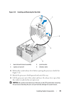
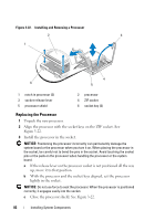
Figure 3-22. Installing and Removing a Processor 2 3 1 4 6 5 1 notch in processor (2) 3 socket-release lever 5 processor shield 2 processor 4 ZIF socket 6 socket key (2) Replacing the Processor 1 Unpack the new processor. 2 Align the processor with the socket keys on the ZIF socket. See Figure 3-22. 3 Install the processor in the socket. NOTICE: Positioning the processor incorrectly can permanently damage the system board or the processor when you turn it on. When placing the processor in the socket, be careful not to bend the pins in the socket. Avoid touching the socket pins or the pads on the processor when handling the processor or the system board. a If the release lever on the processor socket is not positioned all the way up, move it to that position. b With the processor and the socket keys aligned, set the processor lightly in the socket. NOTICE: Do not use force to seat the processor. When the processor is positioned correctly, it engages easily into the socket. c Close the processor shield. See Figure 3-22. 82 Installing System Components
-
 1
1 -
2
-
3
-
4
-
5
-
6
-
7
-
8
-
9
-
10
-
11
-
12
-
13
-
14
-
15
-
16
-
17
-
18
-
19
-
20
-
21
-
22
-
23
-
24
-
25
-
26
-
27
-
28
-
29
-
30
-
31
-
32
-
33
-
34
-
35
-
36
-
37
-
38
-
39
-
40
-
41
-
42
-
43
-
44
-
45
-
46
-
47
-
48
-
49
-
50
-
51
-
52
-
53
-
54
-
55
-
56
-
57
-
58
-
59
-
60
-
61
-
62
-
63
-
64
-
65
-
66
-
67
-
68
-
69
-
70
-
71
-
72
-
73
-
74
-
75
-
76
-
 77
77 -
 78
78 -
 79
79 -
 80
80 -
 81
81 -
 82
82 -
 83
83 -
 84
84 -
 85
85 -
 86
86 -
 87
87 -
88
-
89
-
90
-
91
-
92
-
93
-
94
-
95
-
96
-
97
-
98
-
99
-
100
-
101
-
102
-
103
-
104
-
105
-
106
-
107
-
108
-
109
-
110
-
111
-
112
-
113
-
114
-
115
-
116
-
117
-
118
-
119
-
120
-
121
-
122
-
123
-
124
-
125
-
126
-
127
-
128
-
129
-
130
-
131
-
132
-
133
-
134
-
135
-
136
-
137
-
138
-
139
-
140
-
141
-
142
-
143
-
144
-
145
-
146
-
147
-
148
-
149
-
150
-
151
-
152
-
153
-
154
-
155
-
156
-
157
-
158
 |
 |
