Dell PowerEdge T100 Hardware Owner's Manual - Page 78
When the memory module is properly seated in the connector, the, at each end of the module.
 |
View all Dell PowerEdge T100 manuals
Add to My Manuals
Save this manual to your list of manuals |
Page 78 highlights
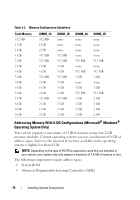
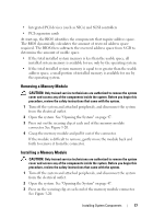
4 Align the memory module's edge connector with the alignment key in the connector. The memory module connector has an alignment key that allows the memory module to be installed in the connector in only one way. 5 Applying even pressure to both ends of the module, insert the module into the connector and carefully press the module into place. Figure 3-20. Installing and Removing a Memory Module 1 4 3 2 1 memory module 3 connector 2 alignment key 4 memory module socket ejectors (2) 6 Pull up on the securing clips to lock the module into place. If you insert the module correctly, the securing clips snap into the cutouts at each end of the module. When the memory module is properly seated in the connector, the securing clips on the memory module socket should align with the securing clips on the other connectors with memory modules installed. 7 Close the system. See "Closing the System" on page 47. 78 Installing System Components
-
 1
1 -
2
-
3
-
4
-
5
-
6
-
7
-
8
-
9
-
10
-
11
-
12
-
13
-
14
-
15
-
16
-
17
-
18
-
19
-
20
-
21
-
22
-
23
-
24
-
25
-
26
-
27
-
28
-
29
-
30
-
31
-
32
-
33
-
34
-
35
-
36
-
37
-
38
-
39
-
40
-
41
-
42
-
43
-
44
-
45
-
46
-
47
-
48
-
49
-
50
-
51
-
52
-
53
-
54
-
55
-
56
-
57
-
58
-
59
-
60
-
61
-
62
-
63
-
64
-
65
-
66
-
67
-
68
-
69
-
70
-
71
-
72
-
 73
73 -
 74
74 -
 75
75 -
 76
76 -
 77
77 -
 78
78 -
 79
79 -
 80
80 -
 81
81 -
 82
82 -
 83
83 -
84
-
85
-
86
-
87
-
88
-
89
-
90
-
91
-
92
-
93
-
94
-
95
-
96
-
97
-
98
-
99
-
100
-
101
-
102
-
103
-
104
-
105
-
106
-
107
-
108
-
109
-
110
-
111
-
112
-
113
-
114
-
115
-
116
-
117
-
118
-
119
-
120
-
121
-
122
-
123
-
124
-
125
-
126
-
127
-
128
-
129
-
130
-
131
-
132
-
133
-
134
-
135
-
136
-
137
-
138
-
139
-
140
-
141
-
142
-
143
-
144
-
145
-
146
-
147
-
148
-
149
-
150
-
151
-
152
-
153
-
154
-
155
-
156
-
157
-
158
 |
 |
