Dell PowerEdge T100 Hardware Owner's Manual - Page 46
Inside the System - processor fan
 |
View all Dell PowerEdge T100 manuals
Add to My Manuals
Save this manual to your list of manuals |
Page 46 highlights
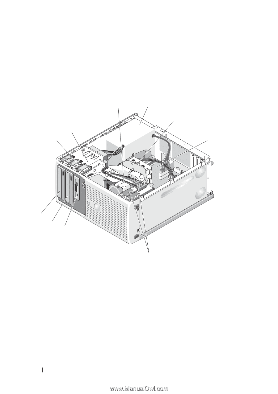
Inside the System In Figure 3-1, the system cover is opened to provide an interior view of the system. Figure 3-1. Inside the System 10 1 9 8 2 3 7 6 5 1 power supply 3 system board 5 3.5-inch drive bay 7 5.25-inch drive bays (2) 9 drive cage 4 2 heat sink and shroud assembly 4 hard drives (2) 6 tape backup unit 8 bezel sliding plate release 10 processor cooling fan The system board can accommodate one processor, four expansion cards, and four memory modules. The hard drive bays provide space for up to two SAS or SATA hard drives. Drive bays in the front of the system provide space for an optical drive, an optional tape drive or second optical drive, and an 46 Installing System Components
-
 1
1 -
2
-
3
-
4
-
5
-
6
-
7
-
8
-
9
-
10
-
11
-
12
-
13
-
14
-
15
-
16
-
17
-
18
-
19
-
20
-
21
-
22
-
23
-
24
-
25
-
26
-
27
-
28
-
29
-
30
-
31
-
32
-
33
-
34
-
35
-
36
-
37
-
38
-
39
-
40
-
 41
41 -
 42
42 -
 43
43 -
 44
44 -
 45
45 -
 46
46 -
 47
47 -
 48
48 -
 49
49 -
 50
50 -
 51
51 -
52
-
53
-
54
-
55
-
56
-
57
-
58
-
59
-
60
-
61
-
62
-
63
-
64
-
65
-
66
-
67
-
68
-
69
-
70
-
71
-
72
-
73
-
74
-
75
-
76
-
77
-
78
-
79
-
80
-
81
-
82
-
83
-
84
-
85
-
86
-
87
-
88
-
89
-
90
-
91
-
92
-
93
-
94
-
95
-
96
-
97
-
98
-
99
-
100
-
101
-
102
-
103
-
104
-
105
-
106
-
107
-
108
-
109
-
110
-
111
-
112
-
113
-
114
-
115
-
116
-
117
-
118
-
119
-
120
-
121
-
122
-
123
-
124
-
125
-
126
-
127
-
128
-
129
-
130
-
131
-
132
-
133
-
134
-
135
-
136
-
137
-
138
-
139
-
140
-
141
-
142
-
143
-
144
-
145
-
146
-
147
-
148
-
149
-
150
-
151
-
152
-
153
-
154
-
155
-
156
-
157
-
158
 |
 |
46
Installing System Components
Inside the System
In Figure 3-1, the system cover is opened to provide an interior view of the
system.
Figure 3-1.
Inside the System
The system board can accommodate one processor, four expansion cards, and
four memory modules. The hard drive bays provide space for up to two SAS
or SATA hard drives. Drive bays in the front of the system provide space for
an optical drive, an optional tape drive or second optical drive, and an
1
power supply
2
heat sink and shroud assembly
3
system board
4
hard drives (2)
5
3.5-inch drive bay
6
tape backup unit
7
5.25-inch drive bays (2)
8
bezel sliding plate release
9
drive cage
10
processor cooling fan
3
2
1
7
5
10
4
8
9
6