Dell PowerEdge T100 Hardware Owner's Manual - Page 79
Microprocessor, Removing the Processor - upgrade
 |
View all Dell PowerEdge T100 manuals
Add to My Manuals
Save this manual to your list of manuals |
Page 79 highlights
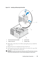
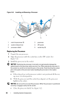
8 Reconnect the system to the electrical outlet, and turn on the system and attached peripherals. The system detects that the new memory does not match the existing configuration information and generates the following message: The amount of system memory has changed. Strike the F1 key to continue, F2 to run the setup utility 9 Press to enter the System Setup program and check the value for Memory Information. See "System Setup Options" on page 30. The system should have changed the value for Memory Information to reflect the newly installed memory. Verify the new value. If it is correct, skip to step 13. 10 If the memory value is incorrect, turn off the system and attached peripherals, and disconnect the system from the electrical outlet. 11 Open the system. See "Opening the System" on page 47. 12 Ensure that the installed memory modules are seated properly in their connectors, and repeat step 7 through step 9. 13 When the Memory Information value is correct, press to exit the System Setup program. 14 Run the system diagnostics to verify that the memory modules are operating properly. See "Running the System Diagnostics" on page 130. Microprocessor You can upgrade the system processor to take advantage of future options in speed and functionality. The processor and its associated internal cache memory are contained in a land grid array (LGA) package that is installed in a ZIF socket on the system board. Removing the Processor CAUTION: Only trained service technicians are authorized to remove the system cover and access any of the components inside the system. Before you begin this procedure, review the safety instructions that came with the system. Installing System Components 79
-
 1
1 -
2
-
3
-
4
-
5
-
6
-
7
-
8
-
9
-
10
-
11
-
12
-
13
-
14
-
15
-
16
-
17
-
18
-
19
-
20
-
21
-
22
-
23
-
24
-
25
-
26
-
27
-
28
-
29
-
30
-
31
-
32
-
33
-
34
-
35
-
36
-
37
-
38
-
39
-
40
-
41
-
42
-
43
-
44
-
45
-
46
-
47
-
48
-
49
-
50
-
51
-
52
-
53
-
54
-
55
-
56
-
57
-
58
-
59
-
60
-
61
-
62
-
63
-
64
-
65
-
66
-
67
-
68
-
69
-
70
-
71
-
72
-
73
-
 74
74 -
 75
75 -
 76
76 -
 77
77 -
 78
78 -
 79
79 -
 80
80 -
 81
81 -
 82
82 -
 83
83 -
 84
84 -
85
-
86
-
87
-
88
-
89
-
90
-
91
-
92
-
93
-
94
-
95
-
96
-
97
-
98
-
99
-
100
-
101
-
102
-
103
-
104
-
105
-
106
-
107
-
108
-
109
-
110
-
111
-
112
-
113
-
114
-
115
-
116
-
117
-
118
-
119
-
120
-
121
-
122
-
123
-
124
-
125
-
126
-
127
-
128
-
129
-
130
-
131
-
132
-
133
-
134
-
135
-
136
-
137
-
138
-
139
-
140
-
141
-
142
-
143
-
144
-
145
-
146
-
147
-
148
-
149
-
150
-
151
-
152
-
153
-
154
-
155
-
156
-
157
-
158
 |
 |
