Dell PowerEdge T100 Hardware Owner's Manual - Page 83
Cooling Fans, Removing the Cooling Fans
 |
View all Dell PowerEdge T100 manuals
Add to My Manuals
Save this manual to your list of manuals |
Page 83 highlights
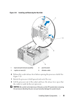
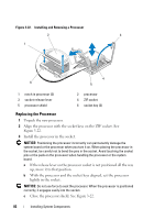
d When the processor is fully seated in the socket, rotate the socket release lever back down until it snaps into place, securing the processor. See Figure 3-22. 4 Clean the thermal grease from the bottom of the heat sink. NOTICE: Ensure that you apply new thermal grease. Applying new thermal grease is critical to ensuring proper thermal bonding as well as optimal processor operation. 5 Apply new thermal grease to the top of the processor. 6 Place the heat sink assembly back onto the heat sink assembly bracket and tilt the heat sink assembly down on the system board. See Figure 3-21. 7 Align the two captive screws properly with the system board, then tighten them to secure the heat sink assembly to the system board. 8 Close the system. See "Closing the System" on page 47. 9 Reconnect the system to the electrical outlet, and turn on the system and attached peripherals. Cooling Fans The system contains two cooling fans, one for the processor and one for the card cage. Each contains a shroud that is part of the cooling fan assembly. The fan and shroud are replaced as a unit. NOTE: If you are removing the larger processor cooling fan, you must first remove the heat sink and shroud assembly. See "Removing the Processor" on page 79 (however, do not remove the processor) and Figure 3-24. Removing the Cooling Fans CAUTION: Only trained service technicians are authorized to remove the system cover and access any of the components inside the system. Before you begin this procedure, review the safety instructions that came with the system. 1 Turn off the system and attached peripherals, and disconnect the system from the electrical outlet. 2 Open the system. See "Opening the System" on page 47. Installing System Components 83
-
 1
1 -
2
-
3
-
4
-
5
-
6
-
7
-
8
-
9
-
10
-
11
-
12
-
13
-
14
-
15
-
16
-
17
-
18
-
19
-
20
-
21
-
22
-
23
-
24
-
25
-
26
-
27
-
28
-
29
-
30
-
31
-
32
-
33
-
34
-
35
-
36
-
37
-
38
-
39
-
40
-
41
-
42
-
43
-
44
-
45
-
46
-
47
-
48
-
49
-
50
-
51
-
52
-
53
-
54
-
55
-
56
-
57
-
58
-
59
-
60
-
61
-
62
-
63
-
64
-
65
-
66
-
67
-
68
-
69
-
70
-
71
-
72
-
73
-
74
-
75
-
76
-
77
-
 78
78 -
 79
79 -
 80
80 -
 81
81 -
 82
82 -
 83
83 -
 84
84 -
 85
85 -
 86
86 -
 87
87 -
 88
88 -
89
-
90
-
91
-
92
-
93
-
94
-
95
-
96
-
97
-
98
-
99
-
100
-
101
-
102
-
103
-
104
-
105
-
106
-
107
-
108
-
109
-
110
-
111
-
112
-
113
-
114
-
115
-
116
-
117
-
118
-
119
-
120
-
121
-
122
-
123
-
124
-
125
-
126
-
127
-
128
-
129
-
130
-
131
-
132
-
133
-
134
-
135
-
136
-
137
-
138
-
139
-
140
-
141
-
142
-
143
-
144
-
145
-
146
-
147
-
148
-
149
-
150
-
151
-
152
-
153
-
154
-
155
-
156
-
157
-
158
 |
 |
