Dell PowerEdge T100 Hardware Owner's Manual - Page 70
Expansion Cards, Removing an Expansion Card
 |
View all Dell PowerEdge T100 manuals
Add to My Manuals
Save this manual to your list of manuals |
Page 70 highlights
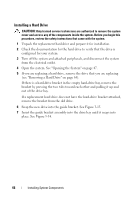
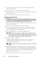
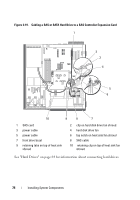
13 Press to enter the System Setup program (see "Entering the System Setup Program" on page 29), and ensure that the drive's controller is enabled. 14 Exit the System Setup program and reboot the system. 15 Partition and logically format the drive. See the documentation for your operating system for instructions. 16 (Optional) Test the hard drive by running the system diagnostics. See "Running the System Diagnostics" on page 129. 17 If the drive you just installed is the primary drive, install your operating system on the hard drive. Expansion Cards The system board can accommodate up to four expansion cards: • One 3.3-V, half-length 32-bit, 33-MHz PCI (slot 3) • One PCIe x1 (slot 4) • One PCIe x4 with x8 slot (slot 1) • One PCIe x8 (slot 2) See Figure 6-2 for the location of the expansion card slots. Removing an Expansion Card CAUTION: Only trained service technicians are authorized to remove the system cover and access any of the components inside the system. Before you begin this procedure, review the safety instructions that came with the system. 1 Turn off the system and attached peripherals, and disconnect the system from the electrical outlet. 2 Open the system. See "Opening the System" on page 47. 3 On the inside of the chassis, press the release tab of the card retention door, and then pull down on the retention door's latch on the outside of the chassis to open the door. See Figure 3-18. 4 If necessary, disconnect any cables from the card. 5 Grasp the card by its top corners and ease it out of its connector. 70 Installing System Components
-
 1
1 -
2
-
3
-
4
-
5
-
6
-
7
-
8
-
9
-
10
-
11
-
12
-
13
-
14
-
15
-
16
-
17
-
18
-
19
-
20
-
21
-
22
-
23
-
24
-
25
-
26
-
27
-
28
-
29
-
30
-
31
-
32
-
33
-
34
-
35
-
36
-
37
-
38
-
39
-
40
-
41
-
42
-
43
-
44
-
45
-
46
-
47
-
48
-
49
-
50
-
51
-
52
-
53
-
54
-
55
-
56
-
57
-
58
-
59
-
60
-
61
-
62
-
63
-
64
-
 65
65 -
 66
66 -
 67
67 -
 68
68 -
 69
69 -
 70
70 -
 71
71 -
 72
72 -
 73
73 -
 74
74 -
 75
75 -
76
-
77
-
78
-
79
-
80
-
81
-
82
-
83
-
84
-
85
-
86
-
87
-
88
-
89
-
90
-
91
-
92
-
93
-
94
-
95
-
96
-
97
-
98
-
99
-
100
-
101
-
102
-
103
-
104
-
105
-
106
-
107
-
108
-
109
-
110
-
111
-
112
-
113
-
114
-
115
-
116
-
117
-
118
-
119
-
120
-
121
-
122
-
123
-
124
-
125
-
126
-
127
-
128
-
129
-
130
-
131
-
132
-
133
-
134
-
135
-
136
-
137
-
138
-
139
-
140
-
141
-
142
-
143
-
144
-
145
-
146
-
147
-
148
-
149
-
150
-
151
-
152
-
153
-
154
-
155
-
156
-
157
-
158
 |
 |
