HP 6125XLG R2306-HP 6125XLG Blade Switch Layer 3 - IP Services Configuration G - Page 113
Basic IP forwarding on the device, FIB table, Displaying FIB table entries
 |
View all HP 6125XLG manuals
Add to My Manuals
Save this manual to your list of manuals |
Page 113 highlights
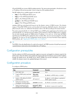
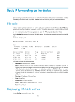
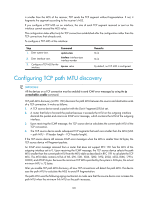
Basic IP forwarding on the device Upon receiving a packet, the device uses the destination IP address of the packet to find a match from the forwarding information base (FIB) table, and then uses the matching entry to forward the packet. FIB table A device selects optimal routes from the routing table, and puts them into the FIB table. Each FIB entry specifies the next hop IP address and output interface for packets destined for a specific subnet or host. For more information about the routing table, see Layer 3-IP Routing Configuration Guide. Use the display fib command to display FIB table entries. The following example displays the entire FIB table. display fib Destination count: 4 FIB entry count: 4 Flag: U:Useable R:Relay G:Gateway F:FRR H:Host B:Blackhole D:Dynamic S:Static Destination/Mask 10.2.0.0/16 10.2.1.1/32 127.0.0.0/8 127.0.0.1/32 Nexthop 10.2.1.1 127.0.0.1 127.0.0.1 127.0.0.1 Flag U UH U UH OutInterface/Token M-GE0/0/0 InLoop0 InLoop0 InLoop0 Label Null Null Null Null A FIB entry includes the following items: • Destination-Destination IP address. • Mask-Network mask. The mask and the destination address identity the destination network. A logical AND operation between the destination address and the network mask yields the address of the destination network. For example, if the destination address is 192.168.1.40 and the mask 255.255.255.0, the address of the destination network is 192.168.1.0. A network mask comprises a certain number of consecutive 1s. It can be expressed in dotted decimal format or by the number of the 1s. • Nexthop-IP address of the next hop. • Flag-Route flag. • OutInterface-Output interface. • Token-MPLS Label Switched Path index number. • Label-Inner label. Displaying FIB table entries Execute display commands in any view. 105
-
 1
1 -
2
-
3
-
4
-
5
-
6
-
7
-
8
-
9
-
10
-
11
-
12
-
13
-
14
-
15
-
16
-
17
-
18
-
19
-
20
-
21
-
22
-
23
-
24
-
25
-
26
-
27
-
28
-
29
-
30
-
31
-
32
-
33
-
34
-
35
-
36
-
37
-
38
-
39
-
40
-
41
-
42
-
43
-
44
-
45
-
46
-
47
-
48
-
49
-
50
-
51
-
52
-
53
-
54
-
55
-
56
-
57
-
58
-
59
-
60
-
61
-
62
-
63
-
64
-
65
-
66
-
67
-
68
-
69
-
70
-
71
-
72
-
73
-
74
-
75
-
76
-
77
-
78
-
79
-
80
-
81
-
82
-
83
-
84
-
85
-
86
-
87
-
88
-
89
-
90
-
91
-
92
-
93
-
94
-
95
-
96
-
97
-
98
-
99
-
100
-
101
-
102
-
103
-
104
-
105
-
106
-
107
-
 108
108 -
 109
109 -
 110
110 -
 111
111 -
 112
112 -
 113
113 -
 114
114 -
 115
115 -
 116
116 -
 117
117 -
 118
118 -
119
-
120
-
121
-
122
-
123
-
124
-
125
-
126
-
127
-
128
-
129
-
130
-
131
-
132
-
133
-
134
-
135
-
136
-
137
-
138
-
139
-
140
-
141
-
142
-
143
-
144
-
145
-
146
-
147
-
148
-
149
-
150
-
151
-
152
-
153
-
154
-
155
-
156
-
157
-
158
-
159
-
160
-
161
-
162
-
163
-
164
-
165
-
166
-
167
-
168
-
169
-
170
-
171
-
172
-
173
-
174
-
175
-
176
-
177
-
178
-
179
-
180
-
181
-
182
-
183
-
184
-
185
-
186
-
187
-
188
-
189
-
190
-
191
-
192
-
193
-
194
-
195
-
196
-
197
-
198
-
199
-
200
-
201
-
202
-
203
-
204
-
205
-
206
-
207
-
208
-
209
-
210
-
211
-
212
-
213
-
214
-
215
-
216
-
217
-
218
-
219
-
220
-
221
-
222
-
223
-
224
-
225
-
226
-
227
-
228
-
229
-
230
 |
 |
