HP 6125XLG R2306-HP 6125XLG Blade Switch Layer 3 - IP Services Configuration G - Page 177
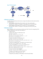
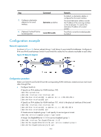
Ping Host B from Host A or ping Host A from Host B. The ping operation succeeds.
 |
View all HP 6125XLG manuals
Add to My Manuals
Save this manual to your list of manuals |
Page 177 highlights
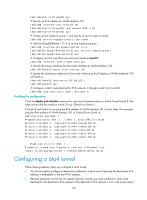
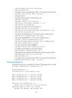
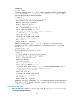
[SwitchA-Tunnel0] source vlan-interface 100 [SwitchA-Tunnel0] quit # Configure a static route destined for 2002::/16 through the tunnel interface. [SwitchA] ipv6 route-static 2002:: 16 tunnel 0 • Configure Switch B: # Specify an IPv4 address for VLAN-interface 100. system-view [SwitchB] interface vlan-interface 100 [SwitchB-Vlan-interface100] ip address 5.1.1.1 24 [SwitchB-Vlan-interface100] quit # Specify a 6to4 address for VLAN-interface 101. [SwitchB] interface vlan-interface 101 [SwitchB-Vlan-interface101] ipv6 address 2002:0501:0101:1::1/64 [SwitchB-Vlan-interface101] quit # Create service loopback group 1 and specify its service type as tunnel. [SwitchB] service-loopback group 1 type tunnel # Assign Ten-GigabitEthernet 1/1/5 to service loopback group 1. [SwitchB] interface Ten-GigabitEthernet 1/1/5 [SwitchB-Ten-GigabitEthernet1/1/5] port service-loopback group 1 [SwitchB-Ten-GigabitEthernet1/1/5] quit # Create a 6to4 tunnel interface tunnel 0. [SwitchB] interface tunnel 0 mode ipv6-ipv4 6to4 # Configure an IPv6 address for the tunnel interface. [SwitchA-Tunnel0] ipv6 address 3002::1/64 # Specify the source interface as VLAN-interface 100 for the tunnel interface. [SwitchB-Tunnel0] source vlan-interface 100 [SwitchB-Tunnel0] quit # Configure a static route destined for 2002::/16 through the tunnel interface. [SwitchB] ipv6 route-static 2002:: 16 tunnel 0 Verifying the configuration # Ping Host B from Host A or ping Host A from Host B. The ping operation succeeds. D:\>ping6 -s 2002:201:101:1::2 2002:501:101:1::2 Pinging 2002:501:101:1::2 from 2002:201:101:1::2 with 32 bytes of data: Reply from 2002:501:101:1::2: bytes=32 time=13ms Reply from 2002:501:101:1::2: bytes=32 time=1ms Reply from 2002:501:101:1::2: bytes=32 time=1ms Reply from 2002:501:101:1::2: bytes=32 time
-
 1
1 -
2
-
3
-
4
-
5
-
6
-
7
-
8
-
9
-
10
-
11
-
12
-
13
-
14
-
15
-
16
-
17
-
18
-
19
-
20
-
21
-
22
-
23
-
24
-
25
-
26
-
27
-
28
-
29
-
30
-
31
-
32
-
33
-
34
-
35
-
36
-
37
-
38
-
39
-
40
-
41
-
42
-
43
-
44
-
45
-
46
-
47
-
48
-
49
-
50
-
51
-
52
-
53
-
54
-
55
-
56
-
57
-
58
-
59
-
60
-
61
-
62
-
63
-
64
-
65
-
66
-
67
-
68
-
69
-
70
-
71
-
72
-
73
-
74
-
75
-
76
-
77
-
78
-
79
-
80
-
81
-
82
-
83
-
84
-
85
-
86
-
87
-
88
-
89
-
90
-
91
-
92
-
93
-
94
-
95
-
96
-
97
-
98
-
99
-
100
-
101
-
102
-
103
-
104
-
105
-
106
-
107
-
108
-
109
-
110
-
111
-
112
-
113
-
114
-
115
-
116
-
117
-
118
-
119
-
120
-
121
-
122
-
123
-
124
-
125
-
126
-
127
-
128
-
129
-
130
-
131
-
132
-
133
-
134
-
135
-
136
-
137
-
138
-
139
-
140
-
141
-
142
-
143
-
144
-
145
-
146
-
147
-
148
-
149
-
150
-
151
-
152
-
153
-
154
-
155
-
156
-
157
-
158
-
159
-
160
-
161
-
162
-
163
-
164
-
165
-
166
-
167
-
168
-
169
-
170
-
171
-
 172
172 -
 173
173 -
 174
174 -
 175
175 -
 176
176 -
 177
177 -
 178
178 -
 179
179 -
 180
180 -
 181
181 -
 182
182 -
183
-
184
-
185
-
186
-
187
-
188
-
189
-
190
-
191
-
192
-
193
-
194
-
195
-
196
-
197
-
198
-
199
-
200
-
201
-
202
-
203
-
204
-
205
-
206
-
207
-
208
-
209
-
210
-
211
-
212
-
213
-
214
-
215
-
216
-
217
-
218
-
219
-
220
-
221
-
222
-
223
-
224
-
225
-
226
-
227
-
228
-
229
-
230
 |
 |