HP 6125XLG R2306-HP 6125XLG Blade Switch Layer 3 - IP Services Configuration G - Page 188
Configuration example, Network requirements, Configuration procedure
 |
View all HP 6125XLG manuals
Add to My Manuals
Save this manual to your list of manuals |
Page 188 highlights
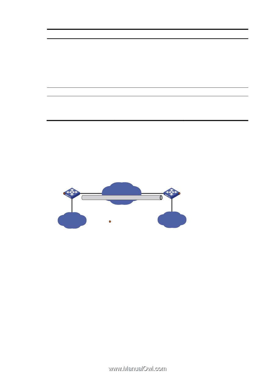
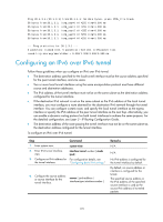
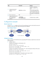
Step Command 5. Configure the destination address for the tunnel interface. destination ipv6-address 6. Return to system view. 7. (Optional.) Enable dropping of IPv6 packets using IPv4-compatible IPv6 addresses. quit tunnel discard ipv4-compatible-packet Remarks By default, no destination address is configured for the tunnel. The tunnel destination address must be the IPv6 address of the receiving interface on the tunnel peer. It is used as the destination IPv6 address of tunneled packets. N/A The default setting is disabled. Configuration example Network requirements As shown in Figure 78, configure an IPv6 over IPv6 tunnel between Switch A and Switch B so the two IP networks can reach each other without disclosing their IPv6 addresses. Figure 78 Network diagram XGE1/1/5 Switch A Vlan-int101 2001::11:1/64 Vlan-int100 2002:1::1/64 Tunnel1 3001::1:1/64 IPv6 network IPv6 over IPv6 tunnel Switch B Vlan-int101 2002::22:1/64 XGE1/1/5 Tunnel2 3001::1:2/64 Vlan-int100 2002:3::1/64 IPv6 group 1 Service loopback port IPv6 group 2 Configuration procedure Make sure Switch A and Switch B have the corresponding VLAN interfaces created and can reach each other through IPv6. • Configure Switch A: # Specify an IPv6 address for VLAN-interface 100. system-view [SwitchA] interface vlan-interface 100 [SwitchA-Vlan-interface100] ipv6 address 2002:1::1 64 [SwitchA-Vlan-interface100] quit # Specify an IPv6 address for VLAN-interface 101, which is the physical interface of the tunnel. [SwitchA] interface vlan-interface 101 [SwitchA-Vlan-interface101] ipv6 address 2001::11:1 64 [SwitchA-Vlan-interface101] quit # Create service loopback group 1 and specify its service type as tunnel. [SwitchA] service-loopback group 1 type tunnel 180
-
 1
1 -
2
-
3
-
4
-
5
-
6
-
7
-
8
-
9
-
10
-
11
-
12
-
13
-
14
-
15
-
16
-
17
-
18
-
19
-
20
-
21
-
22
-
23
-
24
-
25
-
26
-
27
-
28
-
29
-
30
-
31
-
32
-
33
-
34
-
35
-
36
-
37
-
38
-
39
-
40
-
41
-
42
-
43
-
44
-
45
-
46
-
47
-
48
-
49
-
50
-
51
-
52
-
53
-
54
-
55
-
56
-
57
-
58
-
59
-
60
-
61
-
62
-
63
-
64
-
65
-
66
-
67
-
68
-
69
-
70
-
71
-
72
-
73
-
74
-
75
-
76
-
77
-
78
-
79
-
80
-
81
-
82
-
83
-
84
-
85
-
86
-
87
-
88
-
89
-
90
-
91
-
92
-
93
-
94
-
95
-
96
-
97
-
98
-
99
-
100
-
101
-
102
-
103
-
104
-
105
-
106
-
107
-
108
-
109
-
110
-
111
-
112
-
113
-
114
-
115
-
116
-
117
-
118
-
119
-
120
-
121
-
122
-
123
-
124
-
125
-
126
-
127
-
128
-
129
-
130
-
131
-
132
-
133
-
134
-
135
-
136
-
137
-
138
-
139
-
140
-
141
-
142
-
143
-
144
-
145
-
146
-
147
-
148
-
149
-
150
-
151
-
152
-
153
-
154
-
155
-
156
-
157
-
158
-
159
-
160
-
161
-
162
-
163
-
164
-
165
-
166
-
167
-
168
-
169
-
170
-
171
-
172
-
173
-
174
-
175
-
176
-
177
-
178
-
179
-
180
-
181
-
182
-
 183
183 -
 184
184 -
 185
185 -
 186
186 -
 187
187 -
 188
188 -
 189
189 -
 190
190 -
 191
191 -
 192
192 -
 193
193 -
194
-
195
-
196
-
197
-
198
-
199
-
200
-
201
-
202
-
203
-
204
-
205
-
206
-
207
-
208
-
209
-
210
-
211
-
212
-
213
-
214
-
215
-
216
-
217
-
218
-
219
-
220
-
221
-
222
-
223
-
224
-
225
-
226
-
227
-
228
-
229
-
230
 |
 |