HP 6125XLG R2306-HP 6125XLG Blade Switch Layer 3 - IP Services Configuration G - Page 182
Configuration example, Network requirements, Configuration procedure, Con Switch
 |
View all HP 6125XLG manuals
Add to My Manuals
Save this manual to your list of manuals |
Page 182 highlights
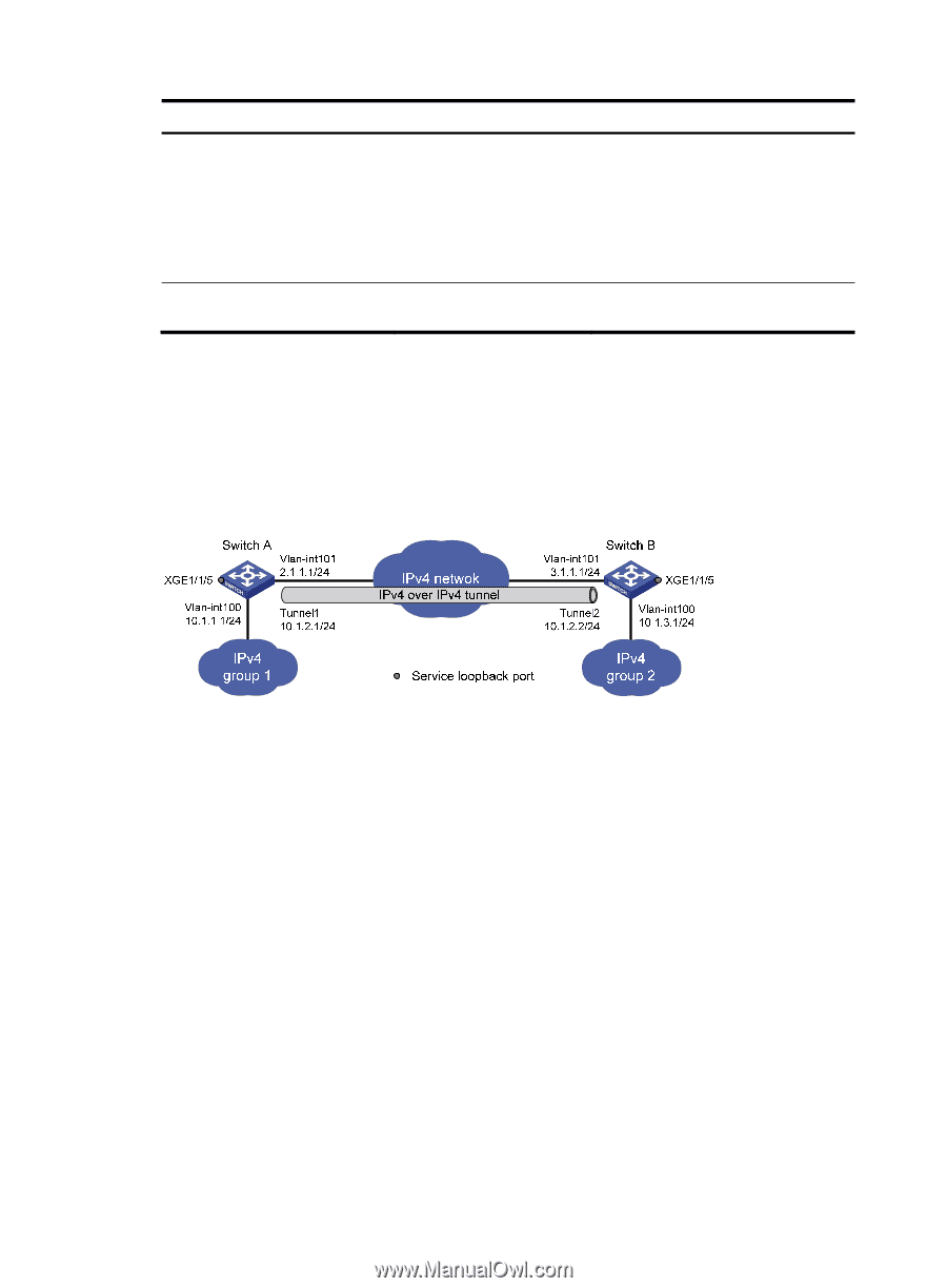
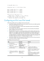
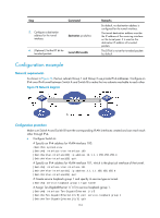
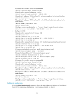
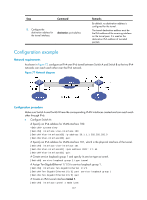
Step Command 5. Configure a destination address for the tunnel interface. destination ip-address 6. (Optional.) Set the DF bit for tunneled packets. tunnel dfbit enable Remarks By default, no destination address is configured for the tunnel interface. The tunnel destination address must be the IP address of the receiving interface on the tunnel peer. It is used as the destination IP address of tunneled packets. The DF bit is not set for tunneled packets by default. Configuration example Network requirements As shown in Figure 76, the two subnets Group 1 and Group 2 use private IPv4 addresses. Configure an IPv4 over IPv4 tunnel between Switch A and Switch B to make the two subnets reachable to each other. Figure 76 Network diagram Configuration procedure Make sure Switch A and Switch B have the corresponding VLAN interfaces created and can reach each other through IPv4. • Configure Switch A: # Specify an IPv4 address for VLAN-interface 100. system-view [SwitchA] interface vlan-interface 100 [SwitchA-Vlan-interface100] ip address 10.1.1.1 255.255.255.0 [SwitchA-Vlan-interface100] quit # Specify an IPv4 address for VLAN-interface 101, which is the physical interface of the tunnel. [SwitchA] interface vlan-interface 101 [SwitchA-Vlan-interface101] ip address 2.1.1.1 255.255.255.0 [SwitchA-Vlan-interface101] quit # Create service loopback group 1 and specify its service type as tunnel. [SwitchA] service-loopback group 1 type tunnel # Assign Ten-GigabitEthernet 1/1/5 to service loopback group 1. [SwitchA] interface Ten-GigabitEthernet 1/1/5 [SwitchA-Ten-GigabitEthernet1/1/5] port service-loopback group 1 [SwitchA-Ten-GigabitEthernet1/1/5] quit 174
-
 1
1 -
2
-
3
-
4
-
5
-
6
-
7
-
8
-
9
-
10
-
11
-
12
-
13
-
14
-
15
-
16
-
17
-
18
-
19
-
20
-
21
-
22
-
23
-
24
-
25
-
26
-
27
-
28
-
29
-
30
-
31
-
32
-
33
-
34
-
35
-
36
-
37
-
38
-
39
-
40
-
41
-
42
-
43
-
44
-
45
-
46
-
47
-
48
-
49
-
50
-
51
-
52
-
53
-
54
-
55
-
56
-
57
-
58
-
59
-
60
-
61
-
62
-
63
-
64
-
65
-
66
-
67
-
68
-
69
-
70
-
71
-
72
-
73
-
74
-
75
-
76
-
77
-
78
-
79
-
80
-
81
-
82
-
83
-
84
-
85
-
86
-
87
-
88
-
89
-
90
-
91
-
92
-
93
-
94
-
95
-
96
-
97
-
98
-
99
-
100
-
101
-
102
-
103
-
104
-
105
-
106
-
107
-
108
-
109
-
110
-
111
-
112
-
113
-
114
-
115
-
116
-
117
-
118
-
119
-
120
-
121
-
122
-
123
-
124
-
125
-
126
-
127
-
128
-
129
-
130
-
131
-
132
-
133
-
134
-
135
-
136
-
137
-
138
-
139
-
140
-
141
-
142
-
143
-
144
-
145
-
146
-
147
-
148
-
149
-
150
-
151
-
152
-
153
-
154
-
155
-
156
-
157
-
158
-
159
-
160
-
161
-
162
-
163
-
164
-
165
-
166
-
167
-
168
-
169
-
170
-
171
-
172
-
173
-
174
-
175
-
176
-
 177
177 -
 178
178 -
 179
179 -
 180
180 -
 181
181 -
 182
182 -
 183
183 -
 184
184 -
 185
185 -
 186
186 -
 187
187 -
188
-
189
-
190
-
191
-
192
-
193
-
194
-
195
-
196
-
197
-
198
-
199
-
200
-
201
-
202
-
203
-
204
-
205
-
206
-
207
-
208
-
209
-
210
-
211
-
212
-
213
-
214
-
215
-
216
-
217
-
218
-
219
-
220
-
221
-
222
-
223
-
224
-
225
-
226
-
227
-
228
-
229
-
230
 |
 |