HP 6125XLG R2306-HP 6125XLG Blade Switch Layer 3 - IP Services Configuration G - Page 144
IPv6 basics configuration example, Network requirements, Configuration procedure
 |
View all HP 6125XLG manuals
Add to My Manuals
Save this manual to your list of manuals |
Page 144 highlights
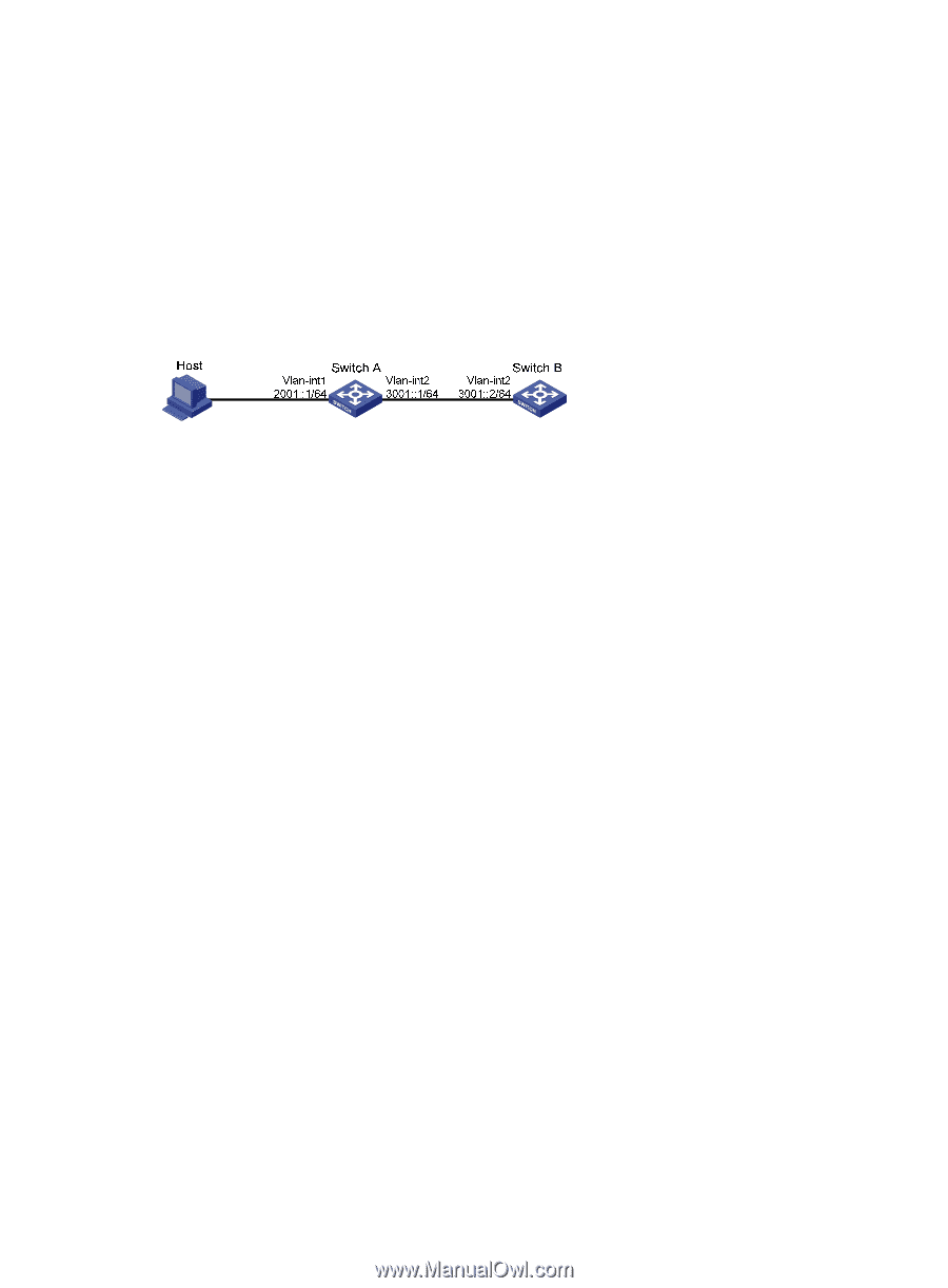
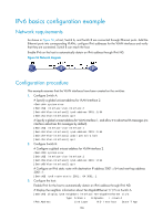
IPv6 basics configuration example Network requirements As shown in Figure 56, a host, Switch A, and Switch B are connected through Ethernet ports. Add the Ethernet ports into corresponding VLANs, configure IPv6 addresses for the VLAN interfaces and verify that they are connected. Switch B can reach the host. Enable IPv6 on the host to automatically obtain an IPv6 address through IPv6 ND. Figure 56 Network diagram Configuration procedure This example assumes that the VLAN interfaces have been created on the switches. 1. Configure Switch A: # Specify a global unicast address for VLAN-interface 2. system-view [SwitchA] interface vlan-interface 2 [SwitchA-Vlan-interface2] ipv6 address 3001::1/64 [SwitchA-Vlan-interface2] quit # Specify a global unicast address for VLAN-interface 1, and allow it to advertise RA messages (no interface advertises RA messages by default). [SwitchA] interface vlan-interface 1 [SwitchA-Vlan-interface1] ipv6 address 2001::1/64 [SwitchA-Vlan-interface1] undo ipv6 nd ra halt [SwitchA-Vlan-interface1] quit 2. Configure Switch B: # Configure a global unicast address for VLAN-interface 2. system-view [SwitchB] interface vlan-interface 2 [SwitchB-Vlan-interface2] ipv6 address 3001::2/64 [SwitchB-Vlan-interface2] quit # Configure an IPv6 static route with destination IP address 2001::/64 and next hop address 3001::1. [SwitchB] ipv6 route-static 2001:: 64 3001::1 3. Configure the host: Enable IPv6 for the host to automatically obtain an IPv6 address through IPv6 ND. # Display the neighbor information about Ten-GigabitEthernet 1/1/5 on Switch A. [SwitchA] display ipv6 neighbors interface Ten-GigabitEthernet 1/1/5 Type: S-Static D-Dynamic I-Invalid IPv6 Address Link Layer VID Interface State T Age 136
-
 1
1 -
2
-
3
-
4
-
5
-
6
-
7
-
8
-
9
-
10
-
11
-
12
-
13
-
14
-
15
-
16
-
17
-
18
-
19
-
20
-
21
-
22
-
23
-
24
-
25
-
26
-
27
-
28
-
29
-
30
-
31
-
32
-
33
-
34
-
35
-
36
-
37
-
38
-
39
-
40
-
41
-
42
-
43
-
44
-
45
-
46
-
47
-
48
-
49
-
50
-
51
-
52
-
53
-
54
-
55
-
56
-
57
-
58
-
59
-
60
-
61
-
62
-
63
-
64
-
65
-
66
-
67
-
68
-
69
-
70
-
71
-
72
-
73
-
74
-
75
-
76
-
77
-
78
-
79
-
80
-
81
-
82
-
83
-
84
-
85
-
86
-
87
-
88
-
89
-
90
-
91
-
92
-
93
-
94
-
95
-
96
-
97
-
98
-
99
-
100
-
101
-
102
-
103
-
104
-
105
-
106
-
107
-
108
-
109
-
110
-
111
-
112
-
113
-
114
-
115
-
116
-
117
-
118
-
119
-
120
-
121
-
122
-
123
-
124
-
125
-
126
-
127
-
128
-
129
-
130
-
131
-
132
-
133
-
134
-
135
-
136
-
137
-
138
-
 139
139 -
 140
140 -
 141
141 -
 142
142 -
 143
143 -
 144
144 -
 145
145 -
 146
146 -
 147
147 -
 148
148 -
 149
149 -
150
-
151
-
152
-
153
-
154
-
155
-
156
-
157
-
158
-
159
-
160
-
161
-
162
-
163
-
164
-
165
-
166
-
167
-
168
-
169
-
170
-
171
-
172
-
173
-
174
-
175
-
176
-
177
-
178
-
179
-
180
-
181
-
182
-
183
-
184
-
185
-
186
-
187
-
188
-
189
-
190
-
191
-
192
-
193
-
194
-
195
-
196
-
197
-
198
-
199
-
200
-
201
-
202
-
203
-
204
-
205
-
206
-
207
-
208
-
209
-
210
-
211
-
212
-
213
-
214
-
215
-
216
-
217
-
218
-
219
-
220
-
221
-
222
-
223
-
224
-
225
-
226
-
227
-
228
-
229
-
230
 |
 |