HP 6125XLG R2306-HP 6125XLG Blade Switch Layer 3 - IP Services Configuration G - Page 116
Configuration procedure, Configuring MTU for an interface, Configuring TCP MSS for an interface
 |
View all HP 6125XLG manuals
Add to My Manuals
Save this manual to your list of manuals |
Page 116 highlights
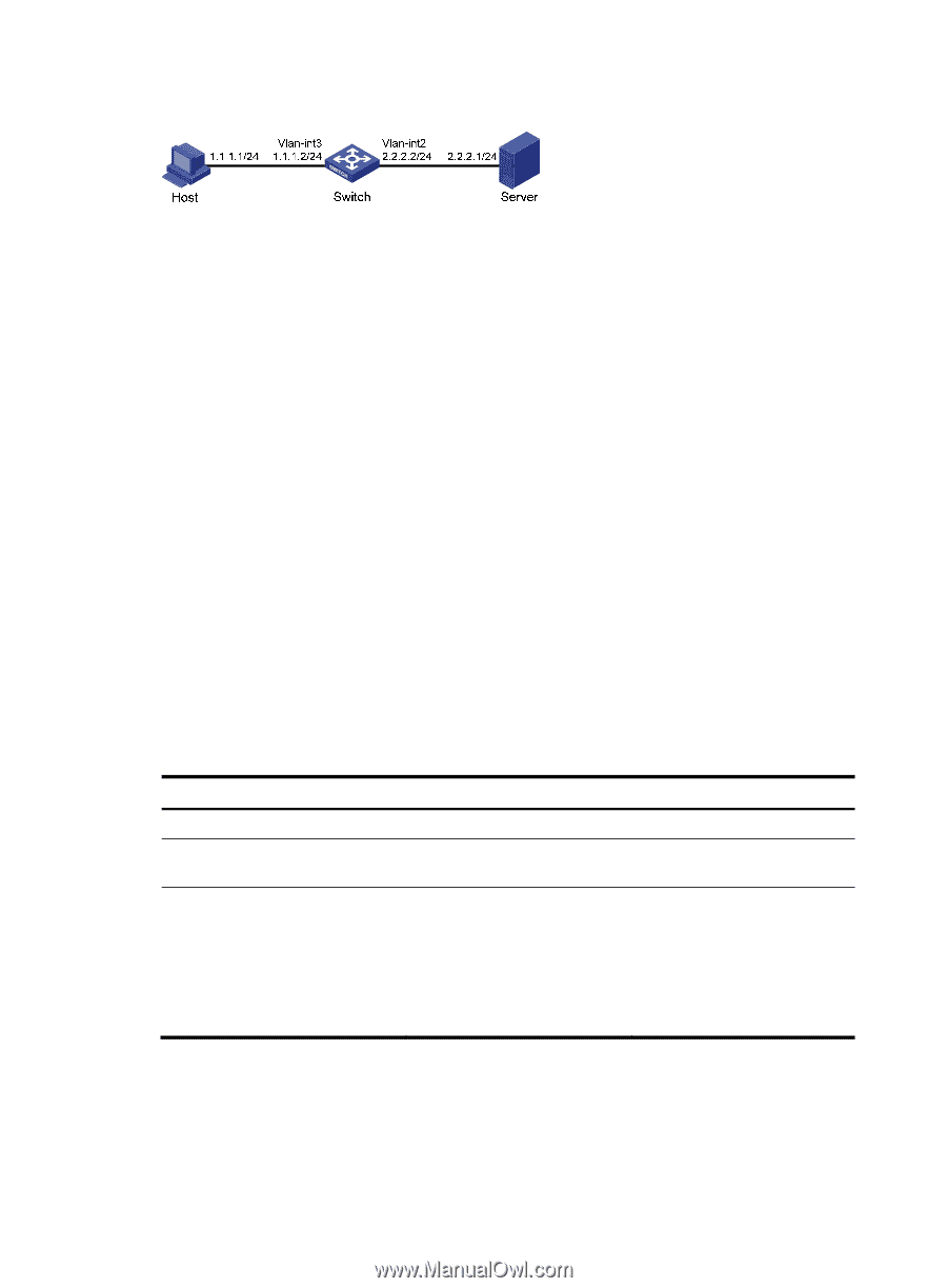
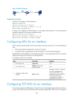
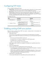
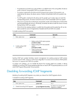
Figure 49 Network diagram Configuration procedure # Specify an IP address for VLAN-interface 3. system-view [Switch] interface vlan-interface 3 [Switch-Vlan-interface3] ip address 1.1.1.2 24 [Switch-Vlan-interface3] quit # Specify an IP address for VLAN-interface 2, and enable VLAN-interface 2 to forward directed broadcasts destined for the directly connected network. [Switch] interface vlan-interface 2 [Switch-Vlan-interface2] ip address 2.2.2.2 24 [Switch-Vlan-interface2] ip forward-broadcast Configuring MTU for an interface When a packet exceeds the MTU of the output interface, the device processes it in one of the following ways: • If the packet disallows fragmentation, the device discards it. • If the packet allows fragmentation, the device fragments it and forwards the fragments. Fragmentation and reassembling consume system resources, so set an appropriate MTU for an interface based on the network environment to avoid fragmentation. To configure an MTU for an interface: Step 1. Enter system view. 2. Enter interface view. Command system-view interface interface-type interface-number 3. Configure an MTU for the interface. ip mtu mtu-size Remarks N/A N/A By default, no MTU is configured. The MTU configured for an interface takes effect on only packets that are sent to the CPU for software forwarding, including packets sent from or destined for this interface. Configuring TCP MSS for an interface The maximum segment size (MSS) option informs the receiver of the largest segment that the sender can accept. Each end announces its MSS during TCP connection establishment. If the size of a TCP segment 108
-
 1
1 -
2
-
3
-
4
-
5
-
6
-
7
-
8
-
9
-
10
-
11
-
12
-
13
-
14
-
15
-
16
-
17
-
18
-
19
-
20
-
21
-
22
-
23
-
24
-
25
-
26
-
27
-
28
-
29
-
30
-
31
-
32
-
33
-
34
-
35
-
36
-
37
-
38
-
39
-
40
-
41
-
42
-
43
-
44
-
45
-
46
-
47
-
48
-
49
-
50
-
51
-
52
-
53
-
54
-
55
-
56
-
57
-
58
-
59
-
60
-
61
-
62
-
63
-
64
-
65
-
66
-
67
-
68
-
69
-
70
-
71
-
72
-
73
-
74
-
75
-
76
-
77
-
78
-
79
-
80
-
81
-
82
-
83
-
84
-
85
-
86
-
87
-
88
-
89
-
90
-
91
-
92
-
93
-
94
-
95
-
96
-
97
-
98
-
99
-
100
-
101
-
102
-
103
-
104
-
105
-
106
-
107
-
108
-
109
-
110
-
 111
111 -
 112
112 -
 113
113 -
 114
114 -
 115
115 -
 116
116 -
 117
117 -
 118
118 -
 119
119 -
 120
120 -
 121
121 -
122
-
123
-
124
-
125
-
126
-
127
-
128
-
129
-
130
-
131
-
132
-
133
-
134
-
135
-
136
-
137
-
138
-
139
-
140
-
141
-
142
-
143
-
144
-
145
-
146
-
147
-
148
-
149
-
150
-
151
-
152
-
153
-
154
-
155
-
156
-
157
-
158
-
159
-
160
-
161
-
162
-
163
-
164
-
165
-
166
-
167
-
168
-
169
-
170
-
171
-
172
-
173
-
174
-
175
-
176
-
177
-
178
-
179
-
180
-
181
-
182
-
183
-
184
-
185
-
186
-
187
-
188
-
189
-
190
-
191
-
192
-
193
-
194
-
195
-
196
-
197
-
198
-
199
-
200
-
201
-
202
-
203
-
204
-
205
-
206
-
207
-
208
-
209
-
210
-
211
-
212
-
213
-
214
-
215
-
216
-
217
-
218
-
219
-
220
-
221
-
222
-
223
-
224
-
225
-
226
-
227
-
228
-
229
-
230
 |
 |