HP 6125XLG R2306-HP 6125XLG Blade Switch Layer 3 - IP Services Configuration G - Page 70
Displaying and maintaining the DHCP client, DHCP client configuration example, Network requirements
 |
View all HP 6125XLG manuals
Add to My Manuals
Save this manual to your list of manuals |
Page 70 highlights
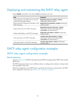
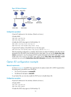
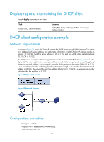
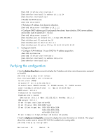
Displaying and maintaining the DHCP client Execute display command in any view. Task Display DHCP client information. Command display dhcp client [ verbose ] [ interface interface-type interface-number ] DHCP client configuration example Network requirements As shown in Figure 25, on a LAN, Switch B contacts the DHCP server through VLAN-interface 2 to obtain an IP address, DNS server address, and static route information. The DHCP client IP address resides on network 10.1.1.0/24. The DNS server address is 20.1.1.1. The next hop of the static route to network 20.1.1.0/24 is 10.1.1.2. The DHCP server uses Option 121 to assign static route information to DHCP clients. Figure 24 shows the Option 121 format. The destination descriptor field contains the following parts: subnet mask length and destination network address. In this example, the value of the destination descriptor field is 18 14 01 01. It is a hexadecimal number indicating that the subnet mask length is 24 and the destination network address is 20.1.1.0. The value of the next hop address field is 0A 01 01 02. It is a hexadecimal number indicating that the next hop is 10.1.1.2. Figure 24 Option 121 format Figure 25 Network diagram Configuration procedure 1. Configure Switch A: # Specify the IP address of VLAN-interface 2. system-view 61
-
 1
1 -
2
-
3
-
4
-
5
-
6
-
7
-
8
-
9
-
10
-
11
-
12
-
13
-
14
-
15
-
16
-
17
-
18
-
19
-
20
-
21
-
22
-
23
-
24
-
25
-
26
-
27
-
28
-
29
-
30
-
31
-
32
-
33
-
34
-
35
-
36
-
37
-
38
-
39
-
40
-
41
-
42
-
43
-
44
-
45
-
46
-
47
-
48
-
49
-
50
-
51
-
52
-
53
-
54
-
55
-
56
-
57
-
58
-
59
-
60
-
61
-
62
-
63
-
64
-
 65
65 -
 66
66 -
 67
67 -
 68
68 -
 69
69 -
 70
70 -
 71
71 -
 72
72 -
 73
73 -
 74
74 -
 75
75 -
76
-
77
-
78
-
79
-
80
-
81
-
82
-
83
-
84
-
85
-
86
-
87
-
88
-
89
-
90
-
91
-
92
-
93
-
94
-
95
-
96
-
97
-
98
-
99
-
100
-
101
-
102
-
103
-
104
-
105
-
106
-
107
-
108
-
109
-
110
-
111
-
112
-
113
-
114
-
115
-
116
-
117
-
118
-
119
-
120
-
121
-
122
-
123
-
124
-
125
-
126
-
127
-
128
-
129
-
130
-
131
-
132
-
133
-
134
-
135
-
136
-
137
-
138
-
139
-
140
-
141
-
142
-
143
-
144
-
145
-
146
-
147
-
148
-
149
-
150
-
151
-
152
-
153
-
154
-
155
-
156
-
157
-
158
-
159
-
160
-
161
-
162
-
163
-
164
-
165
-
166
-
167
-
168
-
169
-
170
-
171
-
172
-
173
-
174
-
175
-
176
-
177
-
178
-
179
-
180
-
181
-
182
-
183
-
184
-
185
-
186
-
187
-
188
-
189
-
190
-
191
-
192
-
193
-
194
-
195
-
196
-
197
-
198
-
199
-
200
-
201
-
202
-
203
-
204
-
205
-
206
-
207
-
208
-
209
-
210
-
211
-
212
-
213
-
214
-
215
-
216
-
217
-
218
-
219
-
220
-
221
-
222
-
223
-
224
-
225
-
226
-
227
-
228
-
229
-
230
 |
 |