HP 6125XLG R2306-HP 6125XLG Blade Switch Layer 3 - IP Services Configuration G - Page 57
Verifying the configuration, Self-defined option configuration example, Network requirements
 |
View all HP 6125XLG manuals
Add to My Manuals
Save this manual to your list of manuals |
Page 57 highlights
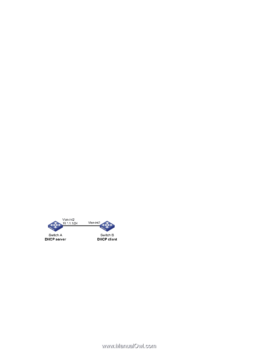
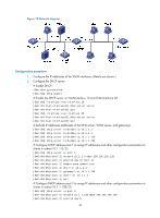
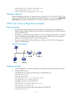
[SwitchB-dhcp-class-tt] if-match option 82 [SwitchB-dhcp-class-tt] quit # Create DHCP address pool aa, specify the address range for the address pool and the address range for user class tt. Specify gateway and DNS server address. [SwitchB] dhcp server ip-pool aa [SwitchB-dhcp-pool-aa] network 10.10.1.0 mask 255.255.255.0 [SwitchB-dhcp-pool-aa] address range 10.10.1.2 10.10.1.100 [SwitchB-dhcp-pool-aa] class tt range 10.10.1.2 10.10.1.10 [SwitchB-dhcp-pool-aa] gateway-list 10.10.1.254 [SwitchB-dhcp-pool-aa] dns-list 10.10.1.20 Verifying the configuration After the preceding configuration is complete, clients in a specific user class in subnet 10.10.1.0/24 can obtain IP addresses and other configuration parameters from the DHCP server (Switch B). Use the display dhcp server ip-in-use command to view the IP address assigned by the DHCP server. Self-defined option configuration example Network requirements As shown in Figure 20, the DHCP client (Switch B) obtains an IP address and PXE server addresses from the DHCP server (Switch A). The IP address belongs to subnet 10.1.1.0/24. The PXE server addresses are 1.2.3.4 and 2.2.2.2. The DHCP server assigns PXE server addresses to DHCP clients through Option 43, a self-defined option. The format of Option 43 and that of the PXE server address sub-option are shown in Figure 14 and Figure 16. The value of Option 43 configured on the DHCP server in this example is 80 0B 00 00 02 01 02 03 04 02 02 02 02. The number 80 is the value of the sub-option type. The number 0B is the value of the sub-option length. The numbers 00 00 are the value of the PXE server type. The number 02 indicates the number of servers. The numbers 01 02 03 04 02 02 02 02 indicate that the PXE server addresses are 1.2.3.4 and 2.2.2.2. Figure 20 Network diagram Configuration procedure 1. Specify IP addresses for the interfaces. (Details not shown.) 2. Configure the DHCP server: # Enable DHCP. system-view [SwitchA] dhcp enable # Enable the DHCP server on VLAN-interface 2. [SwitchA] interface vlan-interface 2 [SwitchA-Vlan-interface2] dhcp select server [SwitchA-Vlan-interface2] quit 48
-
 1
1 -
2
-
3
-
4
-
5
-
6
-
7
-
8
-
9
-
10
-
11
-
12
-
13
-
14
-
15
-
16
-
17
-
18
-
19
-
20
-
21
-
22
-
23
-
24
-
25
-
26
-
27
-
28
-
29
-
30
-
31
-
32
-
33
-
34
-
35
-
36
-
37
-
38
-
39
-
40
-
41
-
42
-
43
-
44
-
45
-
46
-
47
-
48
-
49
-
50
-
51
-
 52
52 -
 53
53 -
 54
54 -
 55
55 -
 56
56 -
 57
57 -
 58
58 -
 59
59 -
 60
60 -
 61
61 -
 62
62 -
63
-
64
-
65
-
66
-
67
-
68
-
69
-
70
-
71
-
72
-
73
-
74
-
75
-
76
-
77
-
78
-
79
-
80
-
81
-
82
-
83
-
84
-
85
-
86
-
87
-
88
-
89
-
90
-
91
-
92
-
93
-
94
-
95
-
96
-
97
-
98
-
99
-
100
-
101
-
102
-
103
-
104
-
105
-
106
-
107
-
108
-
109
-
110
-
111
-
112
-
113
-
114
-
115
-
116
-
117
-
118
-
119
-
120
-
121
-
122
-
123
-
124
-
125
-
126
-
127
-
128
-
129
-
130
-
131
-
132
-
133
-
134
-
135
-
136
-
137
-
138
-
139
-
140
-
141
-
142
-
143
-
144
-
145
-
146
-
147
-
148
-
149
-
150
-
151
-
152
-
153
-
154
-
155
-
156
-
157
-
158
-
159
-
160
-
161
-
162
-
163
-
164
-
165
-
166
-
167
-
168
-
169
-
170
-
171
-
172
-
173
-
174
-
175
-
176
-
177
-
178
-
179
-
180
-
181
-
182
-
183
-
184
-
185
-
186
-
187
-
188
-
189
-
190
-
191
-
192
-
193
-
194
-
195
-
196
-
197
-
198
-
199
-
200
-
201
-
202
-
203
-
204
-
205
-
206
-
207
-
208
-
209
-
210
-
211
-
212
-
213
-
214
-
215
-
216
-
217
-
218
-
219
-
220
-
221
-
222
-
223
-
224
-
225
-
226
-
227
-
228
-
229
-
230
 |
 |