HP 6125XLG R2306-HP 6125XLG Blade Switch Layer 3 - IP Services Configuration G - Page 175
to4 tunnel configuration example, Network requirements
 |
View all HP 6125XLG manuals
Add to My Manuals
Save this manual to your list of manuals |
Page 175 highlights
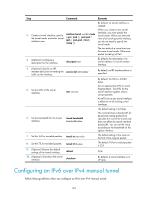
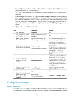
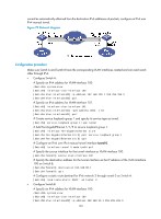
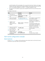
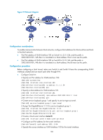
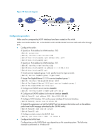
as the IPv6 address of the tunnel interface. You can specify the local tunnel interface as the egress interface of the route or specify the IPv6 address of the peer tunnel interface as the next hop of the route. For the detailed configuration, see Layer 3-IP Routing Configuration Guide. • The automatic tunnel interfaces using the same encapsulation protocol cannot use the same source IP address. To configure a 6to4 tunnel: Step Command Remarks 1. Enter system view. system-view N/A 2. Enter 6to4 tunnel interface interface tunnel number [ mode view. ipv6-ipv4 6to4 ] N/A 3. Specify an IPv6 address for the tunnel interface. For configuration details, see No IPv6 address is configured for the " Configuring basic IPv6 settings." tunnel interface by default. 4. Configure a source address or source interface for the tunnel interface. source { ip-address | interface-type interface-number } By default, no source address or source interface is configured for the tunnel interface. The specified source address or the primary IP address of the specified source interface is used as the source IP address of tunneled packets. 5. (Optional.) Set the DF bit for tunneled packets. tunnel dfbit enable The DF bit is not set for tunneled packets by default. 6. Return to system view. quit N/A 7. (Optional.) Enable dropping of IPv6 packets tunnel discard using IPv4-compatible ipv4-compatible-packet IPv6 addresses. Optional. The default setting is disabled. 6to4 tunnel configuration example Network requirements As shown in Figure 74, configure a 6to4 tunnel between 6to4 switches Switch A and Switch B so Host A and Host B can reach each other over the IPv4 network. 167
-
 1
1 -
2
-
3
-
4
-
5
-
6
-
7
-
8
-
9
-
10
-
11
-
12
-
13
-
14
-
15
-
16
-
17
-
18
-
19
-
20
-
21
-
22
-
23
-
24
-
25
-
26
-
27
-
28
-
29
-
30
-
31
-
32
-
33
-
34
-
35
-
36
-
37
-
38
-
39
-
40
-
41
-
42
-
43
-
44
-
45
-
46
-
47
-
48
-
49
-
50
-
51
-
52
-
53
-
54
-
55
-
56
-
57
-
58
-
59
-
60
-
61
-
62
-
63
-
64
-
65
-
66
-
67
-
68
-
69
-
70
-
71
-
72
-
73
-
74
-
75
-
76
-
77
-
78
-
79
-
80
-
81
-
82
-
83
-
84
-
85
-
86
-
87
-
88
-
89
-
90
-
91
-
92
-
93
-
94
-
95
-
96
-
97
-
98
-
99
-
100
-
101
-
102
-
103
-
104
-
105
-
106
-
107
-
108
-
109
-
110
-
111
-
112
-
113
-
114
-
115
-
116
-
117
-
118
-
119
-
120
-
121
-
122
-
123
-
124
-
125
-
126
-
127
-
128
-
129
-
130
-
131
-
132
-
133
-
134
-
135
-
136
-
137
-
138
-
139
-
140
-
141
-
142
-
143
-
144
-
145
-
146
-
147
-
148
-
149
-
150
-
151
-
152
-
153
-
154
-
155
-
156
-
157
-
158
-
159
-
160
-
161
-
162
-
163
-
164
-
165
-
166
-
167
-
168
-
169
-
 170
170 -
 171
171 -
 172
172 -
 173
173 -
 174
174 -
 175
175 -
 176
176 -
 177
177 -
 178
178 -
 179
179 -
 180
180 -
181
-
182
-
183
-
184
-
185
-
186
-
187
-
188
-
189
-
190
-
191
-
192
-
193
-
194
-
195
-
196
-
197
-
198
-
199
-
200
-
201
-
202
-
203
-
204
-
205
-
206
-
207
-
208
-
209
-
210
-
211
-
212
-
213
-
214
-
215
-
216
-
217
-
218
-
219
-
220
-
221
-
222
-
223
-
224
-
225
-
226
-
227
-
228
-
229
-
230
 |
 |