HP 6125XLG R2306-HP 6125XLG Blade Switch Layer 3 - IP Services Configuration G - Page 66
Configuration procedure, Option 82 configuration example, Network requirements
 |
View all HP 6125XLG manuals
Add to My Manuals
Save this manual to your list of manuals |
Page 66 highlights
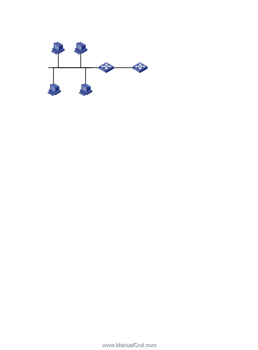
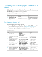
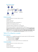
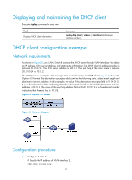
Figure 23 Network diagram DHCP client DHCP client Vlan-int10 10.10.1.1/24 Vlan-int20 10.1.1.2/24 Vlan-int20 10.1.1.1/24 Switch A Switch B DHCP relay agent DHCP server DHCP client DHCP client Configuration procedure # Specify IP addresses for the interfaces. (Details not shown.) # Enable DHCP. system-view [SwitchA] dhcp enable # Enable the DHCP relay agent on VLAN-interface 10. [SwitchA] interface vlan-interface 10 [SwitchA-Vlan-interface10] dhcp select relay # Specify the IP address of the DHCP server on the relay agent. [SwitchA-Vlan-interface10] dhcp relay server-address 10.1.1.1 After the preceding configuration is complete, DHCP clients can obtain IP addresses and other network parameters from the DHCP server through the DHCP relay agent. You can use the display dhcp relay statistics command to view the statistics of DHCP packets forwarded by the DHCP relay agent. If you enable relay entry record on the DHCP relay agent with the dhcp relay client-information record command, you can use the display dhcp relay client-information command to view relay entries. Option 82 configuration example Network requirements As shown in Figure 23, the DHCP relay agent (Switch A) replaces Option 82 in DHCP requests before forwarding them to the DHCP server (Switch B). • The Circuit ID sub-option is company001. • The Remote ID sub-option is device001. To use Option 82, you must also enable the DHCP server to handle Option 82. Configuration procedure # Specify IP addresses for the interfaces. (Details not shown.) # Enable DHCP. system-view [SwitchA] dhcp enable # Enable the DHCP relay agent on VLAN-interface 10. 57
-
 1
1 -
2
-
3
-
4
-
5
-
6
-
7
-
8
-
9
-
10
-
11
-
12
-
13
-
14
-
15
-
16
-
17
-
18
-
19
-
20
-
21
-
22
-
23
-
24
-
25
-
26
-
27
-
28
-
29
-
30
-
31
-
32
-
33
-
34
-
35
-
36
-
37
-
38
-
39
-
40
-
41
-
42
-
43
-
44
-
45
-
46
-
47
-
48
-
49
-
50
-
51
-
52
-
53
-
54
-
55
-
56
-
57
-
58
-
59
-
60
-
 61
61 -
 62
62 -
 63
63 -
 64
64 -
 65
65 -
 66
66 -
 67
67 -
 68
68 -
 69
69 -
 70
70 -
 71
71 -
72
-
73
-
74
-
75
-
76
-
77
-
78
-
79
-
80
-
81
-
82
-
83
-
84
-
85
-
86
-
87
-
88
-
89
-
90
-
91
-
92
-
93
-
94
-
95
-
96
-
97
-
98
-
99
-
100
-
101
-
102
-
103
-
104
-
105
-
106
-
107
-
108
-
109
-
110
-
111
-
112
-
113
-
114
-
115
-
116
-
117
-
118
-
119
-
120
-
121
-
122
-
123
-
124
-
125
-
126
-
127
-
128
-
129
-
130
-
131
-
132
-
133
-
134
-
135
-
136
-
137
-
138
-
139
-
140
-
141
-
142
-
143
-
144
-
145
-
146
-
147
-
148
-
149
-
150
-
151
-
152
-
153
-
154
-
155
-
156
-
157
-
158
-
159
-
160
-
161
-
162
-
163
-
164
-
165
-
166
-
167
-
168
-
169
-
170
-
171
-
172
-
173
-
174
-
175
-
176
-
177
-
178
-
179
-
180
-
181
-
182
-
183
-
184
-
185
-
186
-
187
-
188
-
189
-
190
-
191
-
192
-
193
-
194
-
195
-
196
-
197
-
198
-
199
-
200
-
201
-
202
-
203
-
204
-
205
-
206
-
207
-
208
-
209
-
210
-
211
-
212
-
213
-
214
-
215
-
216
-
217
-
218
-
219
-
220
-
221
-
222
-
223
-
224
-
225
-
226
-
227
-
228
-
229
-
230
 |
 |