HP 6125XLG R2306-HP 6125XLG Blade Switch Layer 3 - IP Services Configuration G - Page 204
Troubleshooting GRE, Symptom, Analysis, Solution
 |
View all HP 6125XLG manuals
Add to My Manuals
Save this manual to your list of manuals |
Page 204 highlights
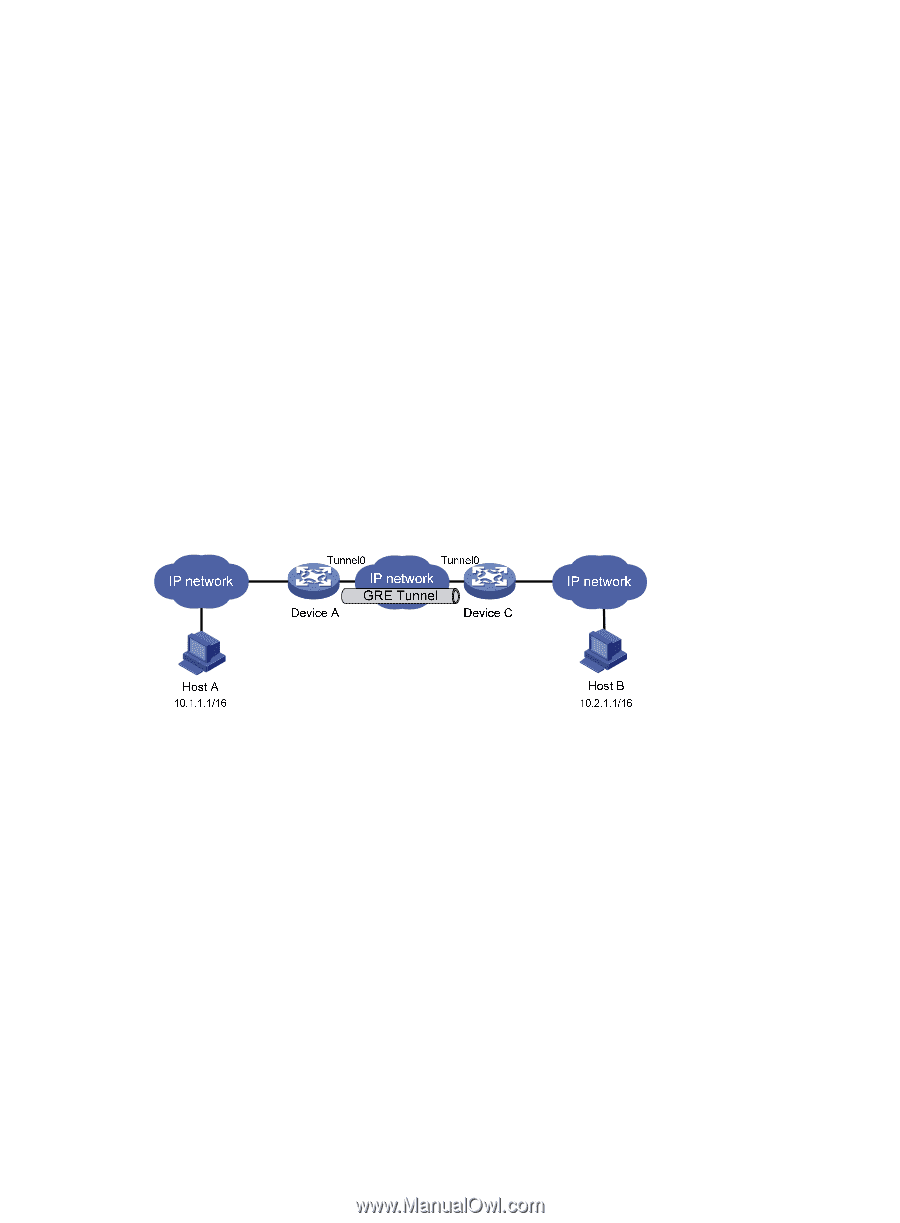
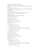
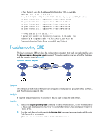
# From Switch B, ping the IP address of VLAN-interface 100 on Switch A. [SwitchB] ping -a 10.1.3.1 10.1.1.1 Ping 10.1.1.1 (10.1.1.1) from 10.1.3.1: 56 data bytes, press CTRL_C to break 56 bytes from 10.1.1.1: icmp_seq=0 ttl=255 time=11.000 ms 56 bytes from 10.1.1.1: icmp_seq=1 ttl=255 time=1.000 ms 56 bytes from 10.1.1.1: icmp_seq=2 ttl=255 time=0.000 ms 56 bytes from 10.1.1.1: icmp_seq=3 ttl=255 time=0.000 ms 56 bytes from 10.1.1.1: icmp_seq=4 ttl=255 time=0.000 ms --- Ping statistics for 10.1.1.1 --5 packet(s) transmitted, 5 packet(s) received, 0.0% packet loss round-trip min/avg/max/stddev = 0.000/2.400/11.000/4.317 ms The output shows that Switch B can successfully ping Switch A. Troubleshooting GRE The key to configuring GRE is to keep the configurations consistent. Most faults can be located by using the debugging gre or debugging tunnel command. This section analyzes one type of fault for illustration, with the scenario shown in Figure 84. Figure 84 Network diagram Symptom The interfaces at both ends of the tunnel are configured correctly and can ping each other, but Host A and Host B cannot ping each other. Analysis It might be because that Device A or Device C has no route to reach the peer network. Solution 1. Execute the display ip routing-table command on Device A and Device C to view whether Device A has a route over tunnel 0 to 10.2.0.0/16 and whether Device C has a route over tunnel 0 to 10.1.0.0/16. 2. If such a route does not exist, execute the ip route-static command in system view to add the route. Take Device A as an example: [DeviceA] ip route-static 10.2.0.0 255.255.0.0 tunnel 0 196
-
 1
1 -
2
-
3
-
4
-
5
-
6
-
7
-
8
-
9
-
10
-
11
-
12
-
13
-
14
-
15
-
16
-
17
-
18
-
19
-
20
-
21
-
22
-
23
-
24
-
25
-
26
-
27
-
28
-
29
-
30
-
31
-
32
-
33
-
34
-
35
-
36
-
37
-
38
-
39
-
40
-
41
-
42
-
43
-
44
-
45
-
46
-
47
-
48
-
49
-
50
-
51
-
52
-
53
-
54
-
55
-
56
-
57
-
58
-
59
-
60
-
61
-
62
-
63
-
64
-
65
-
66
-
67
-
68
-
69
-
70
-
71
-
72
-
73
-
74
-
75
-
76
-
77
-
78
-
79
-
80
-
81
-
82
-
83
-
84
-
85
-
86
-
87
-
88
-
89
-
90
-
91
-
92
-
93
-
94
-
95
-
96
-
97
-
98
-
99
-
100
-
101
-
102
-
103
-
104
-
105
-
106
-
107
-
108
-
109
-
110
-
111
-
112
-
113
-
114
-
115
-
116
-
117
-
118
-
119
-
120
-
121
-
122
-
123
-
124
-
125
-
126
-
127
-
128
-
129
-
130
-
131
-
132
-
133
-
134
-
135
-
136
-
137
-
138
-
139
-
140
-
141
-
142
-
143
-
144
-
145
-
146
-
147
-
148
-
149
-
150
-
151
-
152
-
153
-
154
-
155
-
156
-
157
-
158
-
159
-
160
-
161
-
162
-
163
-
164
-
165
-
166
-
167
-
168
-
169
-
170
-
171
-
172
-
173
-
174
-
175
-
176
-
177
-
178
-
179
-
180
-
181
-
182
-
183
-
184
-
185
-
186
-
187
-
188
-
189
-
190
-
191
-
192
-
193
-
194
-
195
-
196
-
197
-
198
-
 199
199 -
 200
200 -
 201
201 -
 202
202 -
 203
203 -
 204
204 -
 205
205 -
 206
206 -
 207
207 -
 208
208 -
 209
209 -
210
-
211
-
212
-
213
-
214
-
215
-
216
-
217
-
218
-
219
-
220
-
221
-
222
-
223
-
224
-
225
-
226
-
227
-
228
-
229
-
230
 |
 |