HP 6125XLG R2306-HP 6125XLG Blade Switch Layer 3 - IP Services Configuration G - Page 190
Verifying the configuration, Displaying and maintaining tunneling configuration
 |
View all HP 6125XLG manuals
Add to My Manuals
Save this manual to your list of manuals |
Page 190 highlights
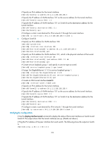
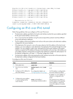
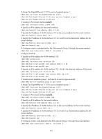
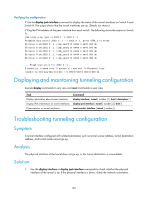
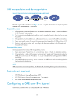
Verifying the configuration # Use the display ipv6 interface command to display the status of the tunnel interfaces on Switch A and Switch B. The output shows that the tunnel interfaces are up. (Details not shown.) # Ping the IPv4 address of the peer interface from each switch. The following shows the output on Switch A. [SwitchA] ping ipv6 -a 2002:1::1 2002:3::1 Ping6(56 data bytes) 2002:1::1 --> 2002:3::1, press CTRL_C to break 56 bytes from 2002:3::1, icmp_seq=0 hlim=64 time=0.000 ms 56 bytes from 2002:3::1, icmp_seq=1 hlim=64 time=0.000 ms 56 bytes from 2002:3::1, icmp_seq=2 hlim=64 time=0.000 ms 56 bytes from 2002:3::1, icmp_seq=3 hlim=64 time=0.000 ms 56 bytes from 2002:3::1, icmp_seq=4 hlim=64 time=0.000 ms --- Ping6 statistics for 2002:3::1 --5 packet(s) transmitted, 5 packet(s) received, 0.0% packet loss round-trip min/avg/max/std-dev = 0.000/0.000/0.000/0.000 ms Displaying and maintaining tunneling configuration Execute display commands in any view and reset commands in user view. Task Command Display information about tunnel interfaces. display interface [ tunnel [ number ] ] [ brief [ description ] ] Display IPv6 information on tunnel interfaces. display ipv6 interface [ tunnel [ number ] ] [ brief ] Clear statistics on tunnel interfaces. reset counters interface [ tunnel [ number ] ] Troubleshooting tunneling configuration Symptom A tunnel interface configured with related parameters such as tunnel source address, tunnel destination address, and tunnel mode cannot go up. Analysis The physical interface of the tunnel does not go up, or the tunnel destination is unreachable. Solution 1. Use the display interface or display ipv6 interface commands to check whether the physical interface of the tunnel is up. If the physical interface is down, check the network connection. 182
-
 1
1 -
2
-
3
-
4
-
5
-
6
-
7
-
8
-
9
-
10
-
11
-
12
-
13
-
14
-
15
-
16
-
17
-
18
-
19
-
20
-
21
-
22
-
23
-
24
-
25
-
26
-
27
-
28
-
29
-
30
-
31
-
32
-
33
-
34
-
35
-
36
-
37
-
38
-
39
-
40
-
41
-
42
-
43
-
44
-
45
-
46
-
47
-
48
-
49
-
50
-
51
-
52
-
53
-
54
-
55
-
56
-
57
-
58
-
59
-
60
-
61
-
62
-
63
-
64
-
65
-
66
-
67
-
68
-
69
-
70
-
71
-
72
-
73
-
74
-
75
-
76
-
77
-
78
-
79
-
80
-
81
-
82
-
83
-
84
-
85
-
86
-
87
-
88
-
89
-
90
-
91
-
92
-
93
-
94
-
95
-
96
-
97
-
98
-
99
-
100
-
101
-
102
-
103
-
104
-
105
-
106
-
107
-
108
-
109
-
110
-
111
-
112
-
113
-
114
-
115
-
116
-
117
-
118
-
119
-
120
-
121
-
122
-
123
-
124
-
125
-
126
-
127
-
128
-
129
-
130
-
131
-
132
-
133
-
134
-
135
-
136
-
137
-
138
-
139
-
140
-
141
-
142
-
143
-
144
-
145
-
146
-
147
-
148
-
149
-
150
-
151
-
152
-
153
-
154
-
155
-
156
-
157
-
158
-
159
-
160
-
161
-
162
-
163
-
164
-
165
-
166
-
167
-
168
-
169
-
170
-
171
-
172
-
173
-
174
-
175
-
176
-
177
-
178
-
179
-
180
-
181
-
182
-
183
-
184
-
 185
185 -
 186
186 -
 187
187 -
 188
188 -
 189
189 -
 190
190 -
 191
191 -
 192
192 -
 193
193 -
 194
194 -
 195
195 -
196
-
197
-
198
-
199
-
200
-
201
-
202
-
203
-
204
-
205
-
206
-
207
-
208
-
209
-
210
-
211
-
212
-
213
-
214
-
215
-
216
-
217
-
218
-
219
-
220
-
221
-
222
-
223
-
224
-
225
-
226
-
227
-
228
-
229
-
230
 |
 |