HP Integrity Superdome 2 HP Integrity Superdome 2 Onboard Administrator User G - Page 120
Enclosure power management, Planning power management, Power and Thermal screen
 |
View all HP Integrity Superdome 2 manuals
Add to My Manuals
Save this manual to your list of manuals |
Page 120 highlights
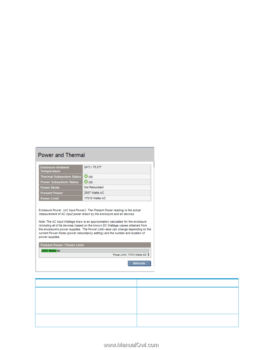
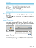
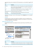
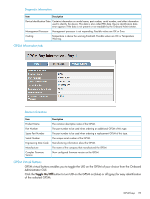
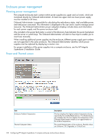
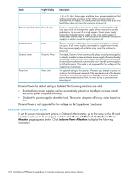
Enclosure power management Planning power management The compute enclosures each contain twelve power supplies (six upper and six lower), which are monitored directly by Onboard Administrator. At least one upper and one lower power supply must be installed at all times. Onboard Administrator is responsible for calculating the redundancy status, total available power, and total power consumed. This information is displayed to the user and is used to manage power resources. The Onboard Administrator power subsystem displays include status and information for each power supply, and the power enclosure itself. Also included in the power fault realm is control of the electronic fuses between the power backplane and the server or switch bays. The Onboard Administrator will alert on fuse trips to enable you to reset fuses manually. When installing additional power supplies into the enclosure, different power supply part numbers are not supported in the same enclosure. The Onboard Administrator identifies which power supplies must be replaced by displaying a caution icon. For proper installation of the power supplies into a compute enclosure, see the HP Integrity Superdome 2 Installation Guide. Power and Thermal screen Item Enclosure Ambient Temperature Thermal Subsystem Status Description This box displays the highest ambient temperature being reported by the installed blade devices. If no blade devices are installed, then this box displays the temperature of the Onboard Administrator module as an approximation of the ambient temperature. The overall thermal status of the enclosure. Possible values are Unknown, OK, Degraded, or Critical Error. 120 Configuring HP Integrity Superdome 2 compute enclosures and enclosure devices
-
 1
1 -
2
-
3
-
4
-
5
-
6
-
7
-
8
-
9
-
10
-
11
-
12
-
13
-
14
-
15
-
16
-
17
-
18
-
19
-
20
-
21
-
22
-
23
-
24
-
25
-
26
-
27
-
28
-
29
-
30
-
31
-
32
-
33
-
34
-
35
-
36
-
37
-
38
-
39
-
40
-
41
-
42
-
43
-
44
-
45
-
46
-
47
-
48
-
49
-
50
-
51
-
52
-
53
-
54
-
55
-
56
-
57
-
58
-
59
-
60
-
61
-
62
-
63
-
64
-
65
-
66
-
67
-
68
-
69
-
70
-
71
-
72
-
73
-
74
-
75
-
76
-
77
-
78
-
79
-
80
-
81
-
82
-
83
-
84
-
85
-
86
-
87
-
88
-
89
-
90
-
91
-
92
-
93
-
94
-
95
-
96
-
97
-
98
-
99
-
100
-
101
-
102
-
103
-
104
-
105
-
106
-
107
-
108
-
109
-
110
-
111
-
112
-
113
-
114
-
 115
115 -
 116
116 -
 117
117 -
 118
118 -
 119
119 -
 120
120 -
 121
121 -
 122
122 -
 123
123 -
 124
124 -
 125
125 -
126
-
127
-
128
-
129
-
130
-
131
-
132
-
133
-
134
-
135
-
136
-
137
-
138
-
139
-
140
-
141
-
142
-
143
-
144
-
145
-
146
-
147
-
148
-
149
-
150
-
151
-
152
-
153
-
154
-
155
-
156
-
157
-
158
-
159
-
160
-
161
-
162
-
163
-
164
-
165
-
166
-
167
-
168
-
169
-
170
-
171
-
172
-
173
-
174
-
175
-
176
-
177
-
178
-
179
-
180
-
181
-
182
-
183
-
184
-
185
-
186
-
187
-
188
-
189
-
190
-
191
 |
 |