HP Integrity Superdome 2 HP Integrity Superdome 2 Onboard Administrator User G - Page 121
Power Management screen
 |
View all HP Integrity Superdome 2 manuals
Add to My Manuals
Save this manual to your list of manuals |
Page 121 highlights
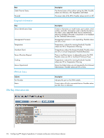
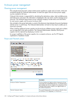
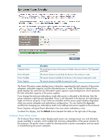
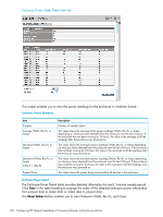
Item Power Subsystem Status Power Mode Present Power Power Limit Description The overall power status of the enclosure. Possible values are Unknown, OK, Degraded, or Critical Error. A user setting to configure the enclosure dc power capacity and the input power redundancy mode of the enclosure. See Power Management for possible values. The amount of watts being consumed by all devices in the enclosure. The maximum amount of power available for consumption by the enclosure measured in watts. NOTE: The Power Limit is dependent on the enclosure power redundancy setting and the number and location of the power supplies in the enclosure. If a Static Power Limit has been specified, the Power Limit displays that limit. Power Management screen To set the power management options in Onboard Administrator, go to the menu on the left and select the enclosure to be managed, and then click Power and Thermal. The Power Management page appears below. Click Power Management to display the following choices: • AC Redundant • Power Supply Redundant • Not Redundant Beneath the main power management choices is the Dynamic Power Savings mode check box which enables you to enable Dynamic Power Savings Mode. The AC Input VA Limit box enables you to set a VA limit for the enclosure. After this limit is met by the enclosure, it will not allow any additional blades, power supplies, fans, or switches to power on. If a value is entered into the VA Limit box that is lower than the now used VA for the enclosure, the enclosure does not power off any devices within the enclosure. However, if a device is powered off, it cannot power on because of the VA limit rule set in the Onboard Administrator power management settings. NOTE: If redundancy mode is set to Redundant, AC Redundant, or Power Supply Redundant, and power redundancy is lost, then you must either add additional power supplies or change the redundancy mode setting in the Onboard Administrator to restore Power Subsystem status. See the Insight Display for corrective steps. The HP Superdome 2 Enclosure power management system enables you to customize the configuration of the enclosure. You can select from the different modes on the Onboard Administrator Power Management screen. The power modes are explained in the following table. Mode Redundant AC Redundant Insight Display name Redundant AC Redundant Description For dc power supplies only. In this configuration, N upper and N lower power supplies are used to provide power and N upper and N lower power supplies are used to provide redundancy (where N can equal 1, 2, or 3). Up to three upper and three lower power supplies can fail without causing the enclosure to fail. When correctly wired with redundant dc line feeds, this configuration also ensures that a dc line feed failure does not cause the enclosure to power off. For ac power supplies only. In this configuration, N upper and N lower power supplies are used to provide power and N upper and N lower power supplies are used to provide redundancy (where N can equal Enclosure power management 121
-
 1
1 -
2
-
3
-
4
-
5
-
6
-
7
-
8
-
9
-
10
-
11
-
12
-
13
-
14
-
15
-
16
-
17
-
18
-
19
-
20
-
21
-
22
-
23
-
24
-
25
-
26
-
27
-
28
-
29
-
30
-
31
-
32
-
33
-
34
-
35
-
36
-
37
-
38
-
39
-
40
-
41
-
42
-
43
-
44
-
45
-
46
-
47
-
48
-
49
-
50
-
51
-
52
-
53
-
54
-
55
-
56
-
57
-
58
-
59
-
60
-
61
-
62
-
63
-
64
-
65
-
66
-
67
-
68
-
69
-
70
-
71
-
72
-
73
-
74
-
75
-
76
-
77
-
78
-
79
-
80
-
81
-
82
-
83
-
84
-
85
-
86
-
87
-
88
-
89
-
90
-
91
-
92
-
93
-
94
-
95
-
96
-
97
-
98
-
99
-
100
-
101
-
102
-
103
-
104
-
105
-
106
-
107
-
108
-
109
-
110
-
111
-
112
-
113
-
114
-
115
-
 116
116 -
 117
117 -
 118
118 -
 119
119 -
 120
120 -
 121
121 -
 122
122 -
 123
123 -
 124
124 -
 125
125 -
 126
126 -
127
-
128
-
129
-
130
-
131
-
132
-
133
-
134
-
135
-
136
-
137
-
138
-
139
-
140
-
141
-
142
-
143
-
144
-
145
-
146
-
147
-
148
-
149
-
150
-
151
-
152
-
153
-
154
-
155
-
156
-
157
-
158
-
159
-
160
-
161
-
162
-
163
-
164
-
165
-
166
-
167
-
168
-
169
-
170
-
171
-
172
-
173
-
174
-
175
-
176
-
177
-
178
-
179
-
180
-
181
-
182
-
183
-
184
-
185
-
186
-
187
-
188
-
189
-
190
-
191
 |
 |