HP Integrity Superdome 2 HP Integrity Superdome 2 Onboard Administrator User G - Page 157
Port mapping, Device bay port mapping for Superdome 2 compute enclosures
 |
View all HP Integrity Superdome 2 manuals
Add to My Manuals
Save this manual to your list of manuals |
Page 157 highlights
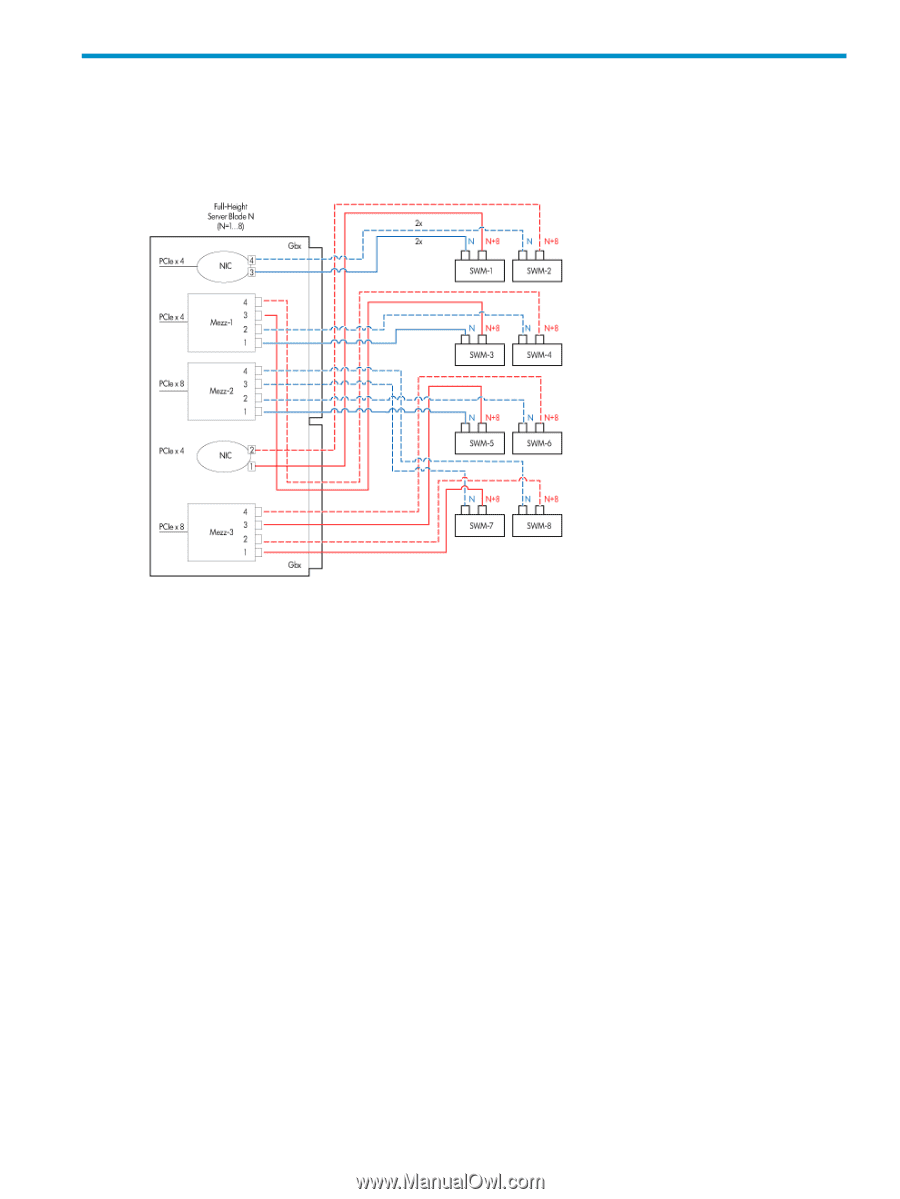
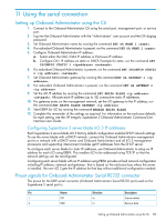
9 Port mapping Device bay port mapping for Superdome 2 compute enclosures Superdome 2 server blade In this diagram, N equals the number of the blade in the enclosure and the port number for the switch. For example, if a blade is inserted into slot 1, it is considered device 1. Because full-height server blades take up the space of two half-height server blades, the enclosure is limited to a maximum of eight full-height server blades. Port mapping from these full-height server blades can initially appear to be different from the half-height server blades, but they use similar conventions. Just as in a half-height server blade, if a blade is inserted into slot 1, it is considered device 1, but it has a second set of ports that also map to switches 1 and 2. With the full-height server blade, an N/N+8 scheme is used on the switches. Therefore, server blade 1 maps to ports 1 and 9 on both switches, as N=1. For a server blade inserted into slot 2, the 4 ports used on switches 1 and 2 are 2 and 10, as N=2. Device bay port mapping tabular view for Superdome 2 compute enclosures If a device is not present, the check box is disabled and the port cannot be viewed. The server blades are mapped to the interconnect bays in the following manner: Superdome 2 server blade • Embedded NICs 1 and 3 (ENET:1 and ENET:3) map to interconnect bay 1. • Embedded NICs 2 and 4 (ENET:2 and ENET:4) map to interconnect bay 2. • Mezzanine 1 ports 1 through 4 map to interconnect bays 3 and 4. • Mezzanine 2 ports 1 and 2 map to interconnect bays 5 and 6. • Mezzanine 2 ports 3 and 4 map to interconnect bays 7 and 8. • Mezzanine 3 (full-height only) ports 1 and 2 map to interconnect bays 7 and 8. • Mezzanine 3 (full-height only) ports 3 and 4 map to interconnect bays 5 and 6. Device bay port mapping for Superdome 2 compute enclosures 157
-
 1
1 -
2
-
3
-
4
-
5
-
6
-
7
-
8
-
9
-
10
-
11
-
12
-
13
-
14
-
15
-
16
-
17
-
18
-
19
-
20
-
21
-
22
-
23
-
24
-
25
-
26
-
27
-
28
-
29
-
30
-
31
-
32
-
33
-
34
-
35
-
36
-
37
-
38
-
39
-
40
-
41
-
42
-
43
-
44
-
45
-
46
-
47
-
48
-
49
-
50
-
51
-
52
-
53
-
54
-
55
-
56
-
57
-
58
-
59
-
60
-
61
-
62
-
63
-
64
-
65
-
66
-
67
-
68
-
69
-
70
-
71
-
72
-
73
-
74
-
75
-
76
-
77
-
78
-
79
-
80
-
81
-
82
-
83
-
84
-
85
-
86
-
87
-
88
-
89
-
90
-
91
-
92
-
93
-
94
-
95
-
96
-
97
-
98
-
99
-
100
-
101
-
102
-
103
-
104
-
105
-
106
-
107
-
108
-
109
-
110
-
111
-
112
-
113
-
114
-
115
-
116
-
117
-
118
-
119
-
120
-
121
-
122
-
123
-
124
-
125
-
126
-
127
-
128
-
129
-
130
-
131
-
132
-
133
-
134
-
135
-
136
-
137
-
138
-
139
-
140
-
141
-
142
-
143
-
144
-
145
-
146
-
147
-
148
-
149
-
150
-
151
-
 152
152 -
 153
153 -
 154
154 -
 155
155 -
 156
156 -
 157
157 -
 158
158 -
 159
159 -
 160
160 -
 161
161 -
 162
162 -
163
-
164
-
165
-
166
-
167
-
168
-
169
-
170
-
171
-
172
-
173
-
174
-
175
-
176
-
177
-
178
-
179
-
180
-
181
-
182
-
183
-
184
-
185
-
186
-
187
-
188
-
189
-
190
-
191
 |
 |