HP LH4r HP NetRAID-4M Installation Guide - Page 17
Installing the Controller Card, The HP NetRAID-4M produces optimum
 |
View all HP LH4r manuals
Add to My Manuals
Save this manual to your list of manuals |
Page 17 highlights
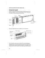
Installing the Hardware DIMM. The DIMM and batteries are "sandwiched" between the PCI card and Daughter Card. In the event of a power loss the battery can continue powering the nonvolatile DIMM for several days. Note: After installation of the HP NetRAID-4M is complete, the batteries automatically begin a charge cycle which lasts until it reaches full charge (up to three hours). During this time the batteries will have sufficient charge to protect the NVRAM data against accidental power breaks, but may not be able to provide the minimum holdover time until they reach full charge. For a list of supported DIMMs and their battery holdover times, see Appendix E, Specifications. See Chapter 8, Understanding The Battery Subsystem for more information on the battery subsystem. Installing the Controller Card 1 Turn OFF power to the computer, and disconnect the power cord. 2 Remove the cover from the computer case. (If necessary, refer to the instructions in your computer documentation.) 3 Locate an unused, unobstructed, 64- or 32-bit PCI expansion slot that supports bus mastering. Unscrew and remove the expansion slot bracket that covers the card-slot opening. Note: The HP NetRAID-4M produces optimum performance when installed in a 64-bit PCI slot but it will operate in a 32-bit expansion slot. Before installing the controller in the PCI slot, ensure that the battery enable jumper is connected to both jumper pins. To locate the battery enable jumper (also know as the J3 jumper) see Figure 2-2. You do not have to remove the daughter card from the main card to connect the battery enable jumper. 2-3
-
 1
1 -
2
-
3
-
4
-
5
-
6
-
7
-
8
-
9
-
10
-
11
-
 12
12 -
 13
13 -
 14
14 -
 15
15 -
 16
16 -
 17
17 -
 18
18 -
 19
19 -
 20
20 -
 21
21 -
 22
22 -
23
-
24
-
25
-
26
-
27
-
28
-
29
-
30
-
31
-
32
-
33
-
34
-
35
-
36
-
37
-
38
-
39
-
40
-
41
-
42
-
43
-
44
-
45
-
46
-
47
-
48
-
49
-
50
-
51
-
52
-
53
-
54
-
55
-
56
-
57
-
58
-
59
-
60
-
61
-
62
-
63
-
64
-
65
-
66
-
67
-
68
-
69
-
70
-
71
-
72
-
73
-
74
-
75
-
76
-
77
-
78
-
79
-
80
-
81
-
82
-
83
-
84
-
85
-
86
-
87
-
88
-
89
-
90
-
91
-
92
-
93
-
94
-
95
-
96
-
97
-
98
-
99
-
100
-
101
-
102
-
103
-
104
-
105
-
106
-
107
-
108
-
109
-
110
-
111
-
112
-
113
-
114
-
115
-
116
-
117
-
118
-
119
-
120
-
121
-
122
-
123
-
124
 |
 |